The nRF52840 implements "access port protection" that prevents the existing Hatsu firmware from being dumped. This means that you cannot restore your Hatsu to factory settings after you flash ZMK.
DISCLAIMER: THE CASE OF THE HATSU MUST BE OPENED. THE RUBBER FEET AND THEIR ADHESIVE MAY BE PERMANENTLY DAMAGED IN THE PROCESS. TO PURCHASE ADDITIONAL FEET PLEASE CONTACT ME OR ANGRY MIAO
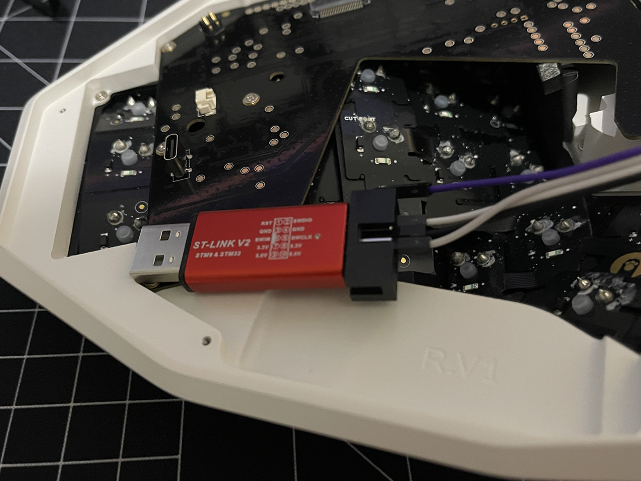
To program the Hatsu, you must have a hardware debugger. Using an ST-Link V2 or a clone will be perfectly fine.
These debuggers are known to work:
Official:
https://www.adafruit.com/product/2548
Aideepen:
https://www.amazon.com/dp/B01J7N3RE6?psc=1&ref=ppx_yo2ov_dt_b_product_details
It is required to install OpenOCD to control the ST-Link for programming purposes.
$ apt install openocd
$ brew install openocd
Install here: https://gnutoolchains.com/arm-eabi/openocd/
Or, using Chocolatey:
$ choco install openocd
Remove all rubber feet from the bottom of the Hatsu. These feet may be permanently damaged by this removal so be prepared with replacement feet.
Next, remove all of the screws holding the bottom plate of the Hatsu to the case. Be very careful when removing the bottom plate, as the battery is glued to it. It is possible to damage the battery connector by removing the bottom plate too quickly.
Next, remove the battery and bottom plate assembly. Keep it close by.
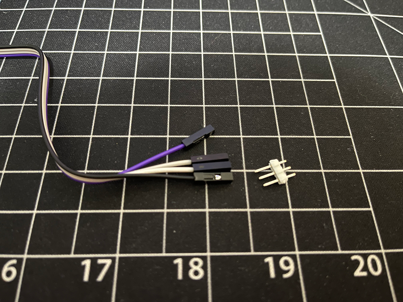
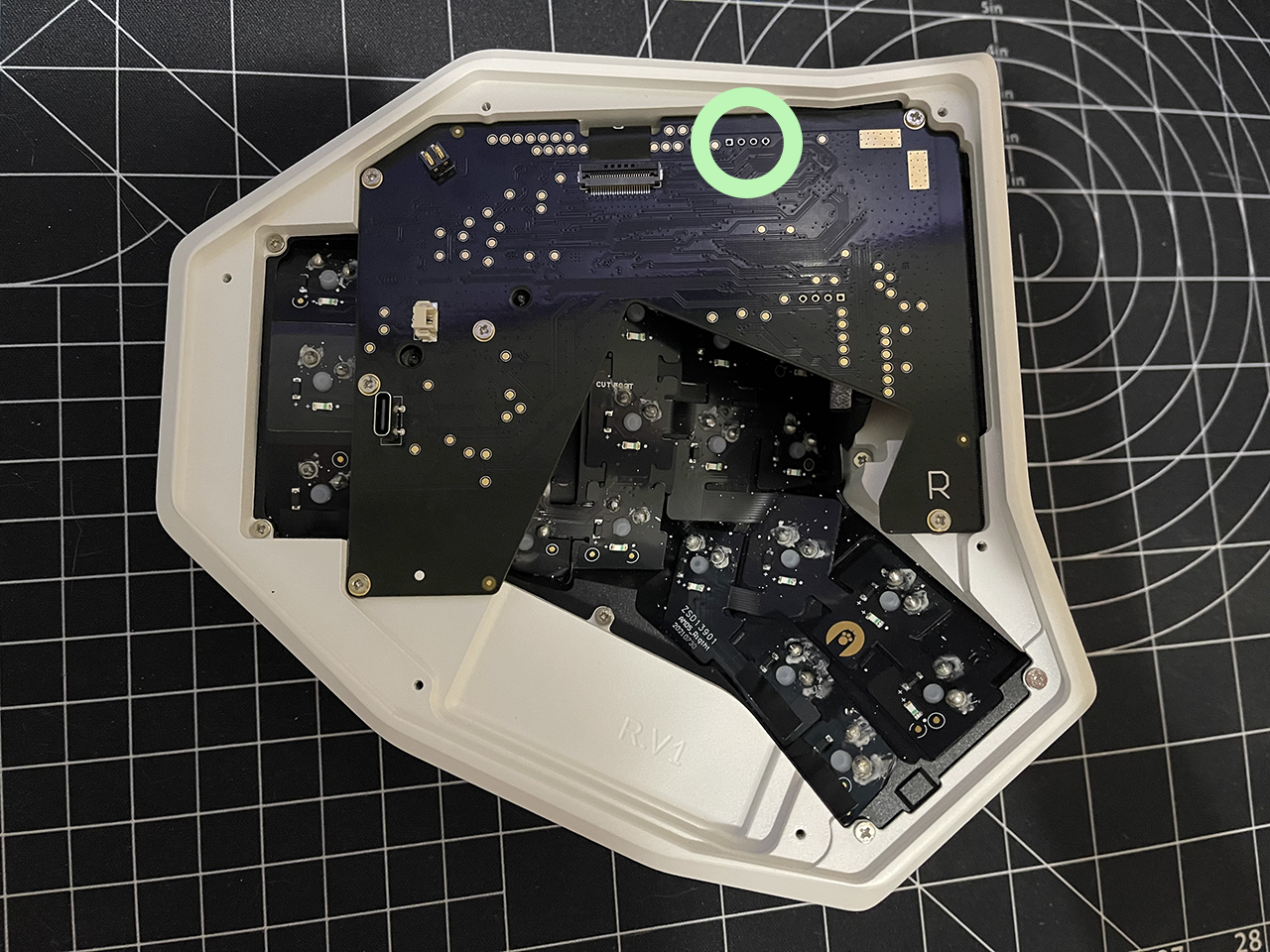
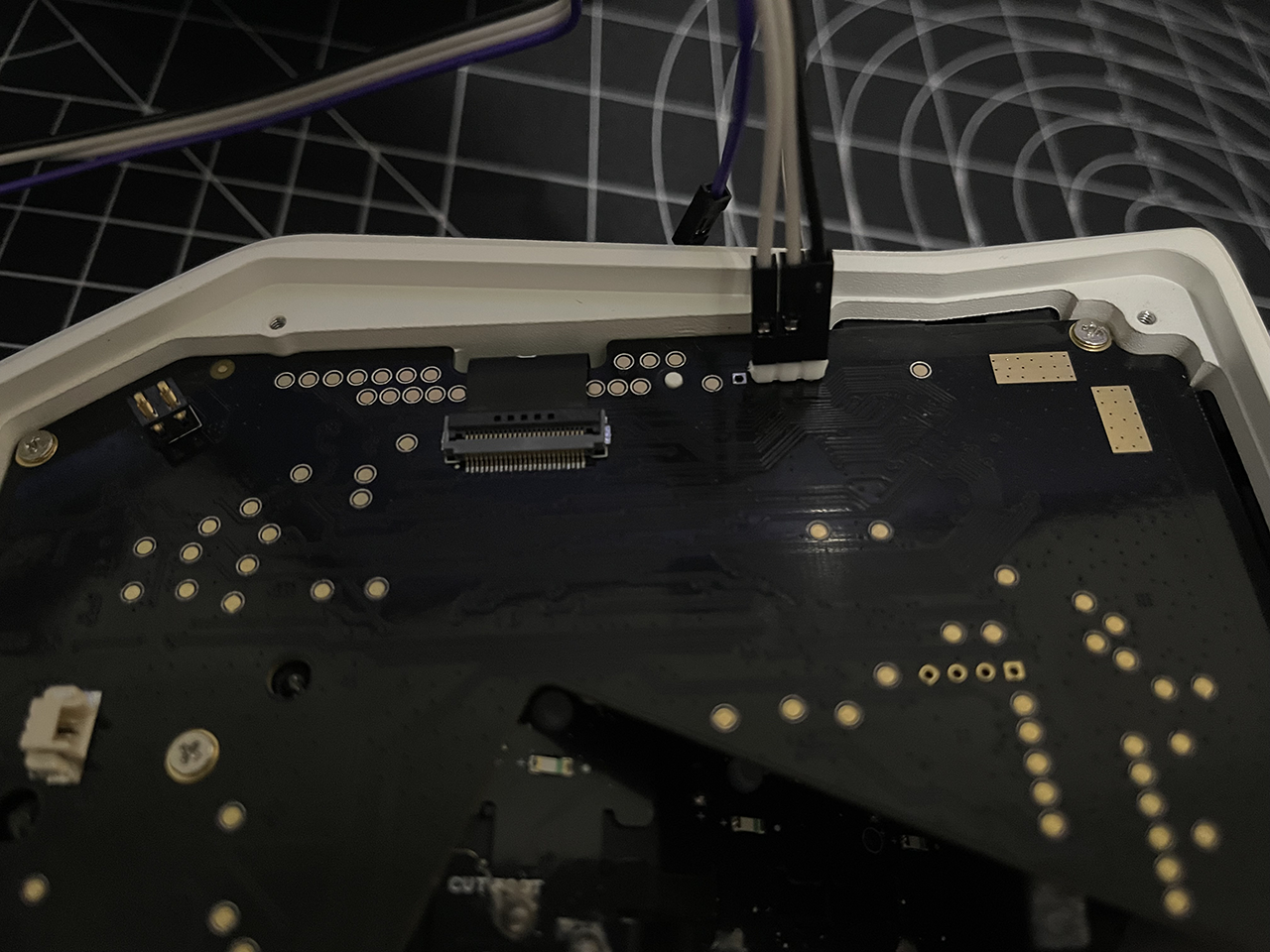
Using the DuPont connectors, connect the "GND," "SWDIO," and "SWCLK" pins to the ST-Link. Your pinout may look different from the picture below!
You will then insert 3 male headers into the other end of the DuPont connectors to hold them together.
Match the pinout to the pinout on the board. This is as follows:
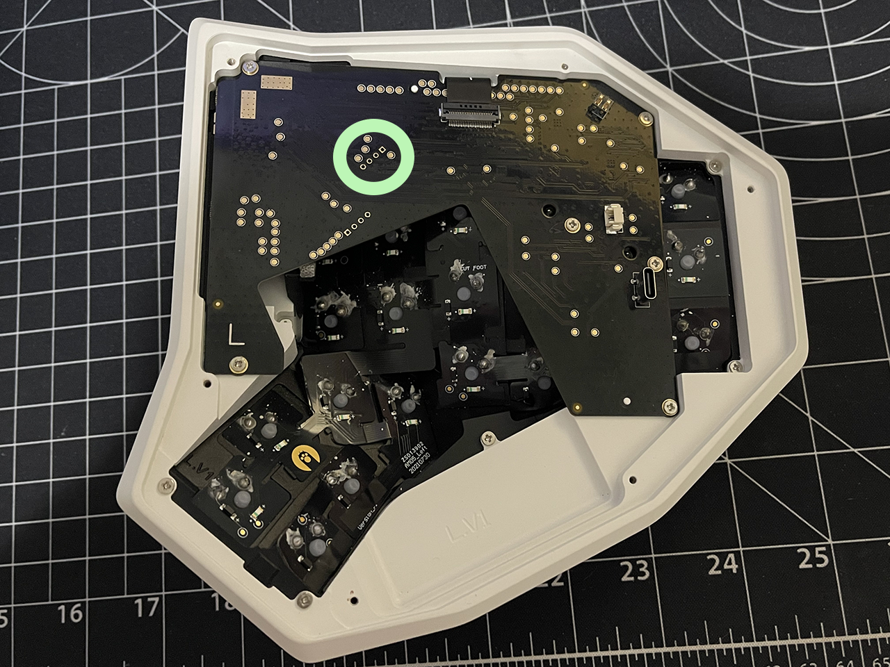
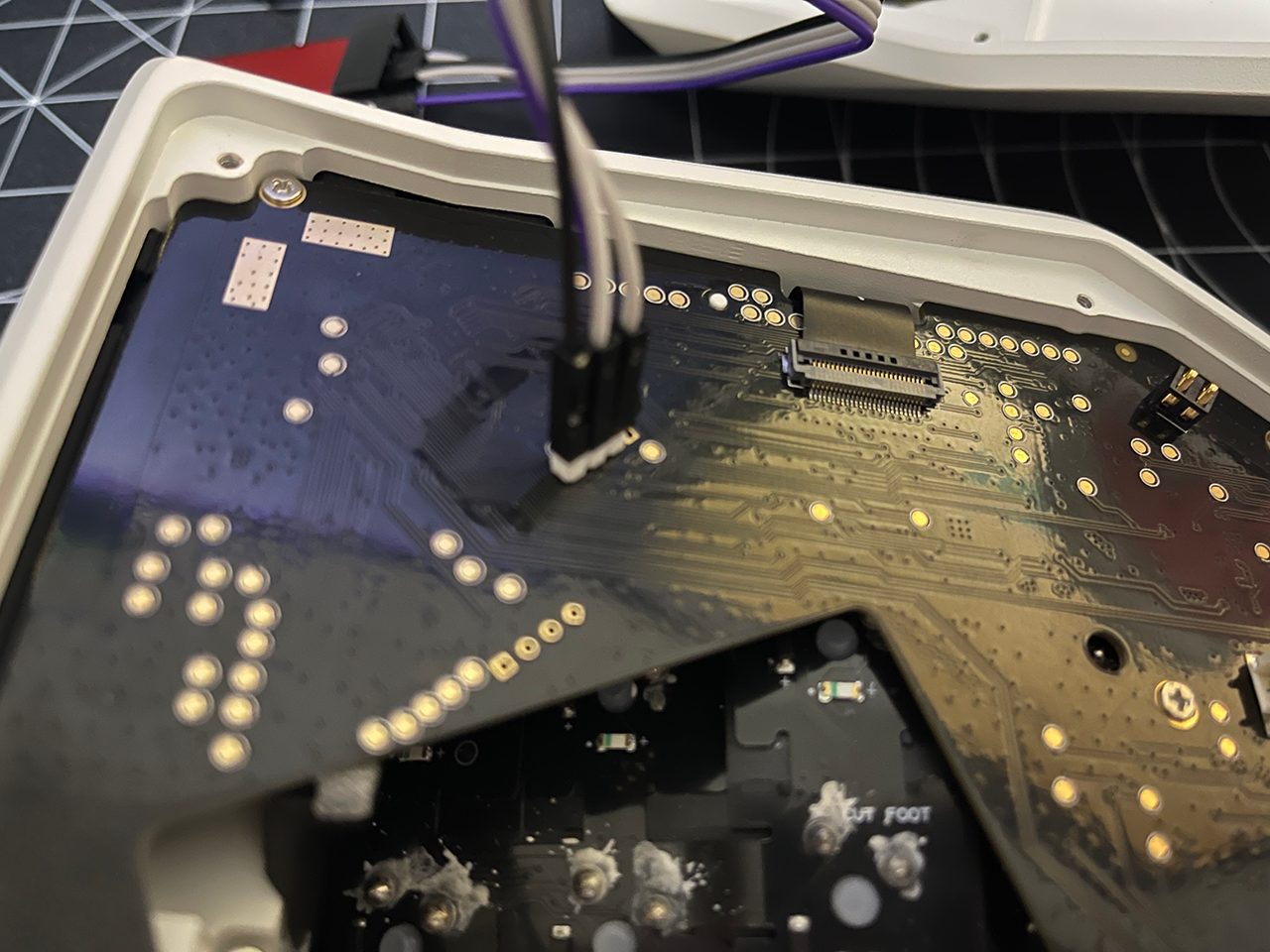
Next, insert these pins into the SWD port of the Hatsu. The location differs on the left and right halves.
Left
Right
Finally, connect the Hatsu's USB-C to power the board.
NOTE: The order of operations must be followed very carefully so that your halves will pair with one another.
"Keeping the batteries disconnected keeps them from binding to eachother as you're flashing them. Maybe less important on the very first try, but if you have to try more than once, then I think it's important." -zpriddy
With the pins inserted into the through holes, tilt them slightly so that they make good contact.
If you are on Linux or MacOS, run the script "flashing/flash.sh"
If you are on Windows, run the script "flashing/flash.bat"
This programs the nRF52840 USB bootloader.
You should see a flash drive appear on your computer titled "AM_HATSU"
Disconnect all batteries from each half.
Begin by flashing the right half. Copy the right.uf2 to the AM_HATSU drive.
Flash the left by copying the left.uf2 to the AM_HATSU drive. Do not connect its battery yet.
Connect the right half's battery.
With the left still connected via USB, plug in its battery. Both halves should successfully pair and bond.

