Hi! My name is Luiz, I am an aspiring game developer and in this repository I will be putting the projects I will create throughout my journey. I will be trying to roughly follow this roadmap by Chris Ohk. Many of the projects you will see here are inspired by two of my favorite content creators, I absolutely recommend you to check them out:
I would also recommend you to check out this other creators who do not (necessarily) inspired the content of this repository, but are a solid option to learn about game art, design, optimization, marketing and development in general:
Without further ado, let's get to the projects!
 I made a video essay about this topic, you can check it out here!
Marching Cubes is a procedural polygonization algorithm that will generate natural looking meshes based on a grid of points. It is a very popular technique used in applications like terrain generation, fluid simulation, voxel rendering and many others. The technique was first described by William E. Lorensen and H. E. Cline in 1987.
The algorithm works by creating a tridimensional grid of points, where each point has a value (often refereed at as "density") that indicates whether the points is located at the interior or the exterior of the mesh. The code slides (marches) a cube through the grid and creates polygons by interpolation of the position of adjacent points. The polygons are then connected to form a mesh.
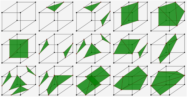
Image from Shamshad Alam's blog
There are 256 possible formations for a cube, however, some of them are redundant as they represent rotations of other formations, leaving us with 15 unique formations. Each formation is represented by a 12-bit integer, one bit per edge, where 1 indicates the presence of a triangle vertex on that edge whilst 0 represents the absence.
My implementation of this algorithm was inspired by this video by Sebastian Lague. The first version of my code used CPU generated chunks, unlike Sebastian's implementation which used compute shaders to make the mesh generation parallel, thus, it was able to have more polygons being generated without heaving great impact on performance. Eventually I also got my implementation to use compute shaders and I will put a side-by-side comparison down bellow. I tried not to look at his code, which is also available on Github in order not to be biased in any way during my implementation, however there were some moments when I used his source code as a reference (for instance, when trying to figure out how the heck was I supposed to know how many triangles my shader had generated).
The example presented on the MarchingCubes.unity scene has three main mono behavior classes: the surface manager and the CPU and GPU chunks. The surface manager is responsible for creating, deleting and updating the chunks according to the position of the player. The chunk is responsible for generating the mesh and updating it when necessary.
The surface manager is a singleton that is associated with a prefab where you can manage the mesh settings like chunk size, chunk resolution, number of chunks per batch and whatnot. The surface manager is also where you select whether you want to use the CPU or GPU implementation.
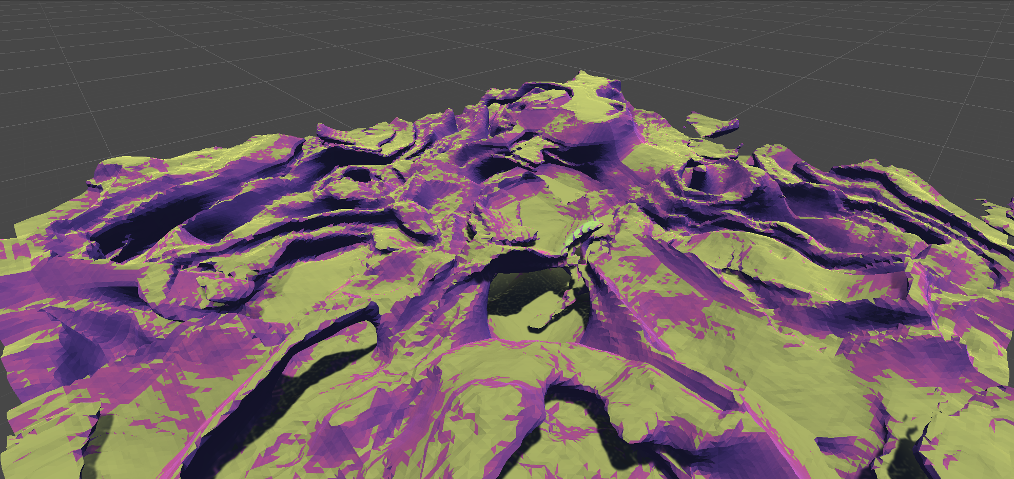
Each chunk generates the values for the points in his grid and uses the tables in Tables.cs to generate the mesh triangles accordingly. The mesh is then updated and rendered. Right now the meshes are generated with RNG for the CPU implementation and with noise maps for the GPU implementation, you will probably notice that the noise map based generation gives us much more organic looking meshes.
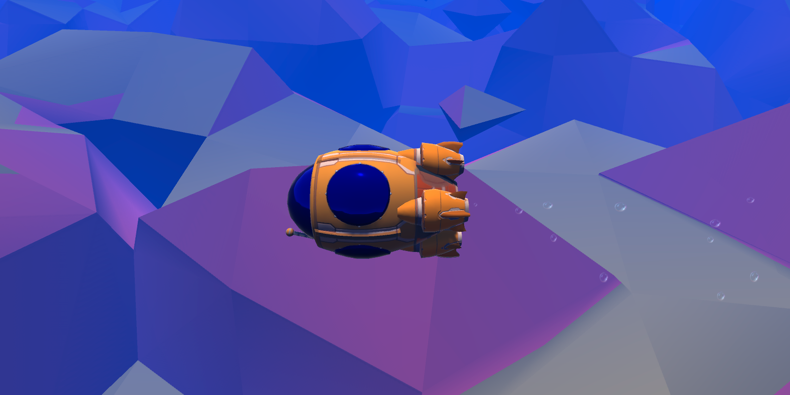
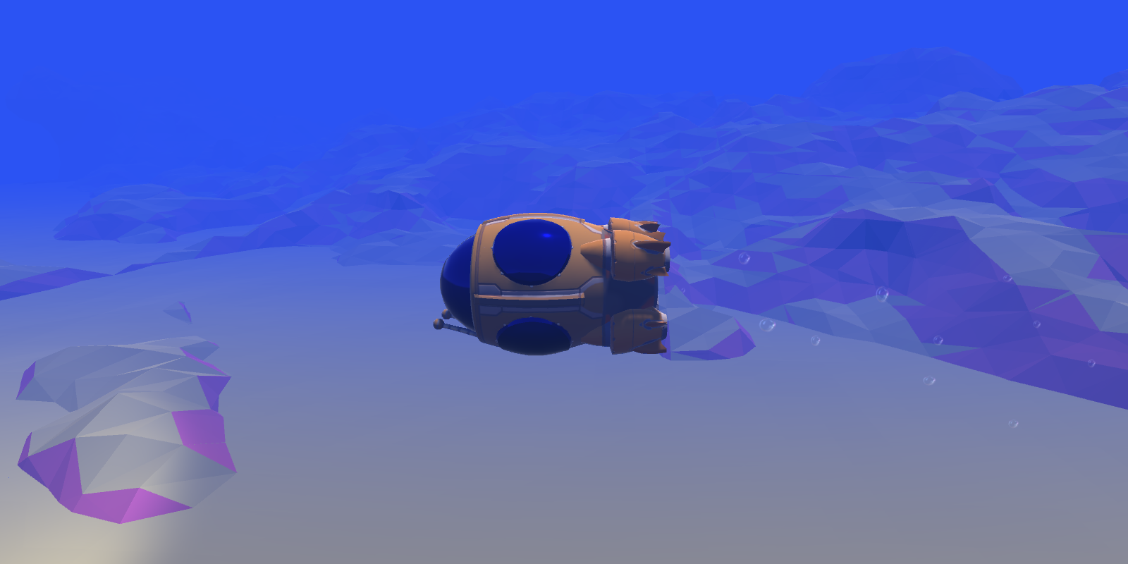
You can check out a video of the result for the first version here, when I had not yet implemented the GPU version, and the second version here, using compute shaders and with an enhanced environment. On the screen shots below you can also see the difference between the CPU (left) and GPU (right) implementations.
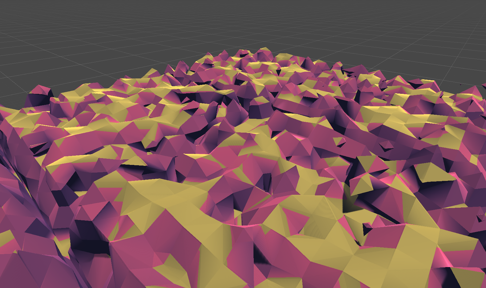
You can also see down below how much more natural the Perlin noise based generation looks compared to the RNG based generation.
⬇️ RNG based ⬇️
⬇️ Perlin noise based ⬇️
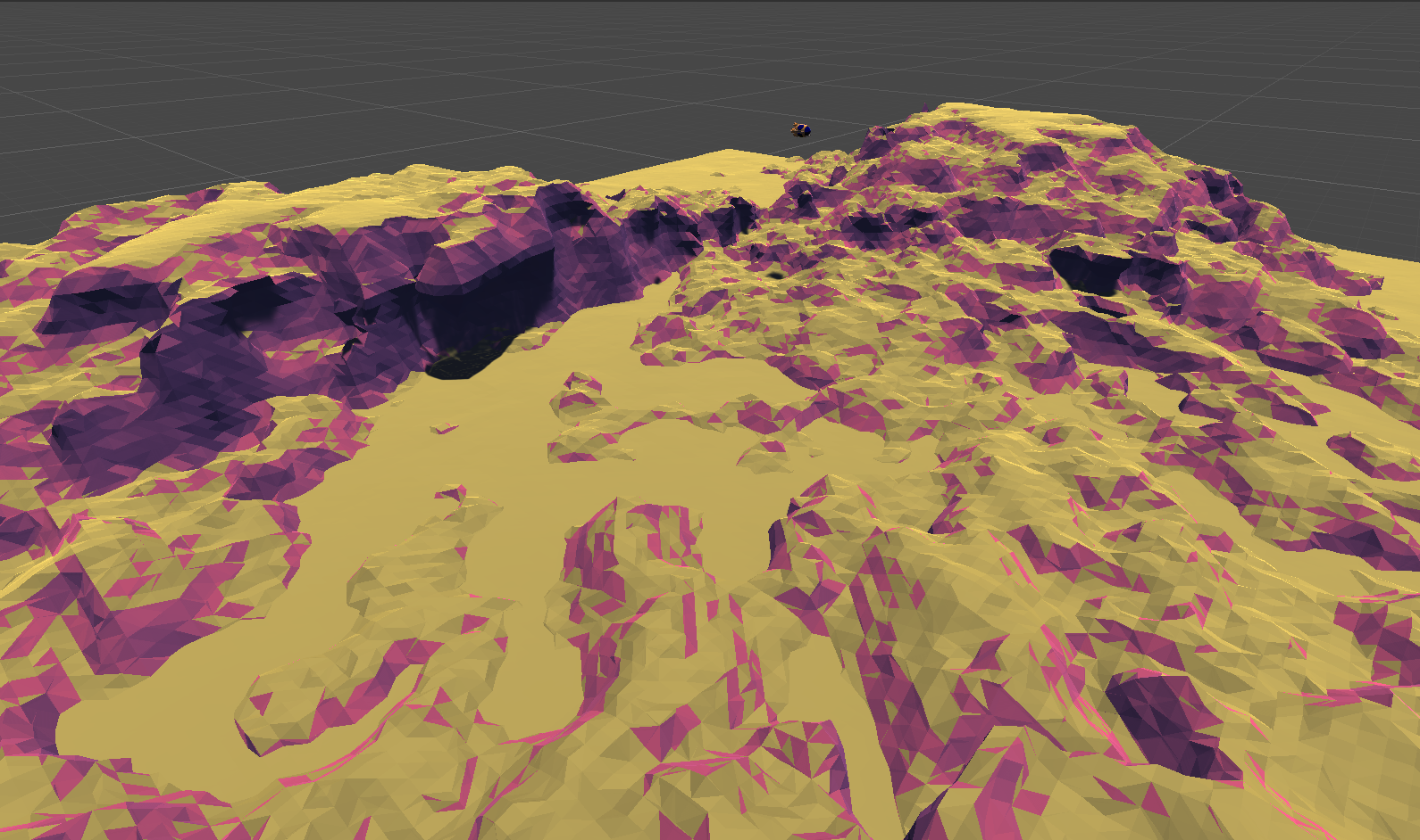
To make the resulting terrain even more intricate, I also implemented position warping, which is basically adding noise to our positions before calculating their density values. This will create complex structures like caves, bridges, cliffs and underpasses. An overview of the resulting terrain can be seen in this video as well as on the screen shot below.
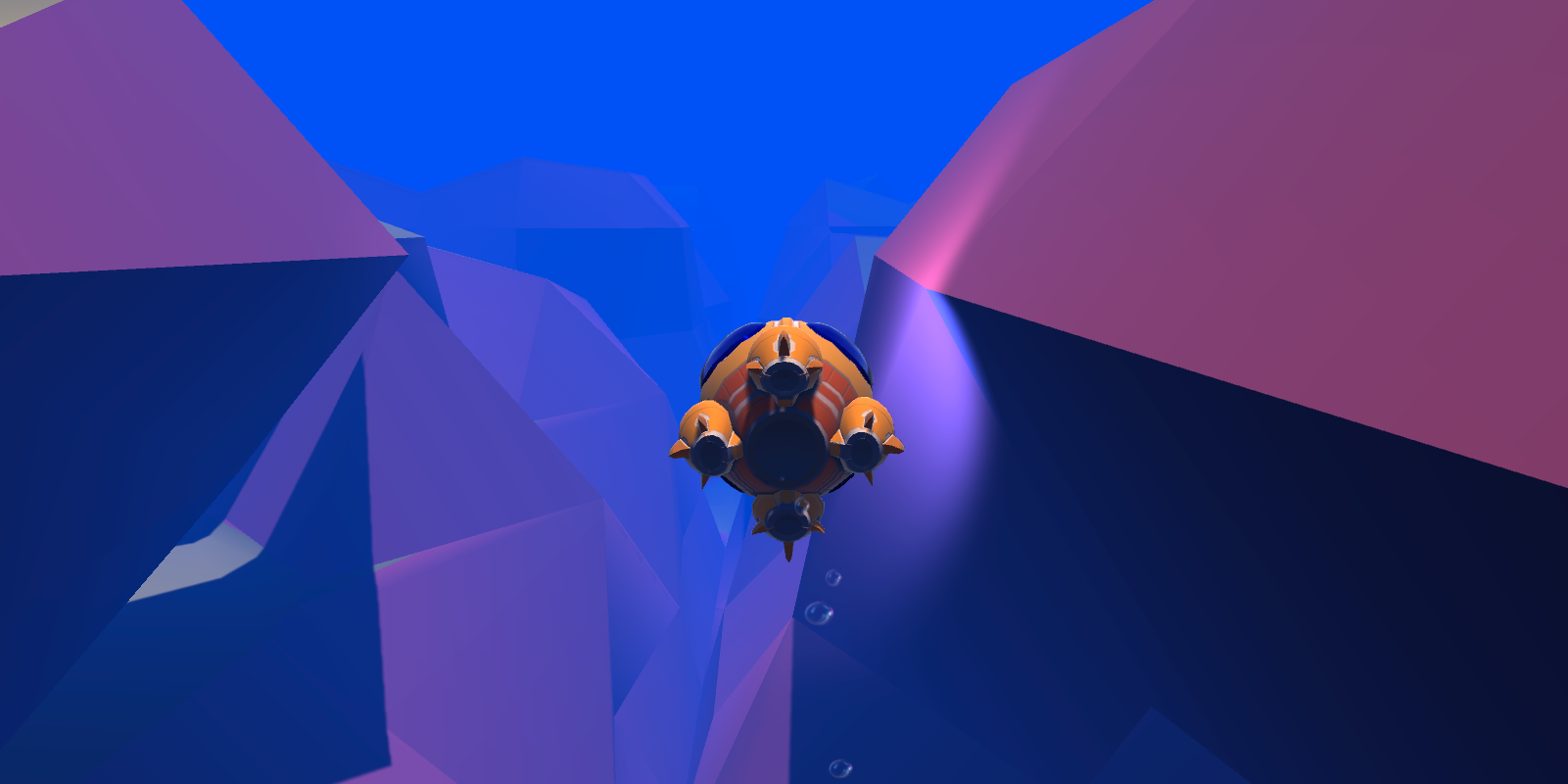
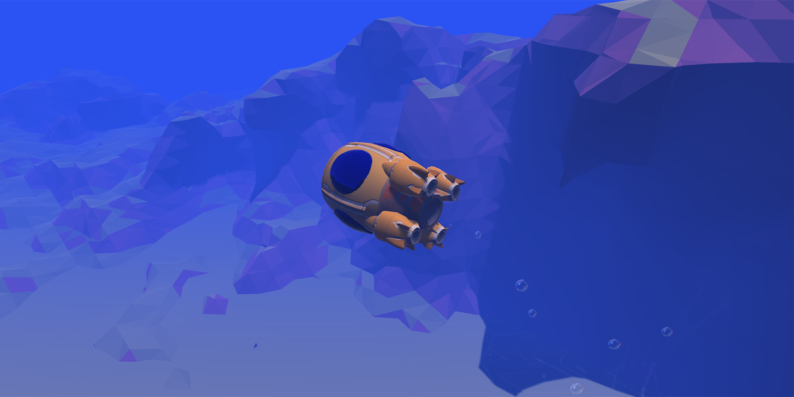
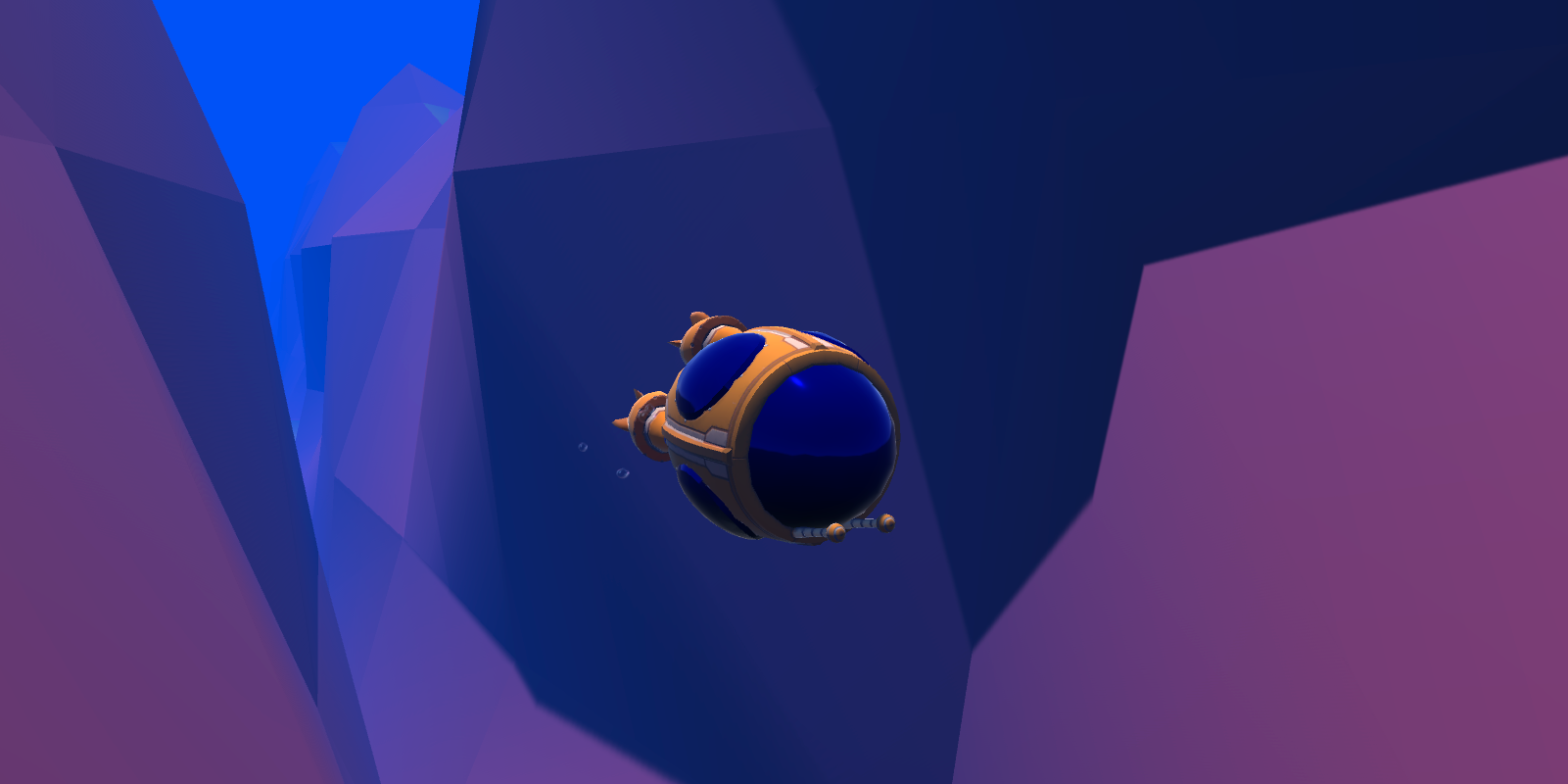
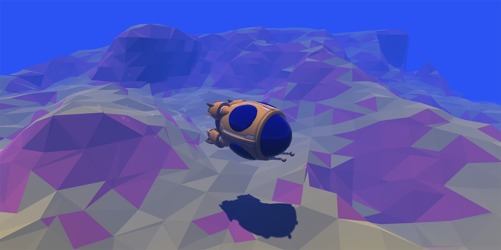
Just to add some polish to the scene I also got a new model for the submarine, implemented a few effects like the water surface foam and underwater fog, detailed vegetation and particle effects. I will probably be continuously evolving this project as I come up with new ideas, but for an overview of the central concepts, check out the video essay linked in the results section!
One very cool feature that can be easily implemented when you use marching cubes for terrain generation is terraforming. Since our mesh is based on a grid of weighted points, to create a terraforming effect you can simply add or remove from the density of the points in a certain area. If we then update the mesh we will get a nice smooth transition between the old and the new terrain. To a smoother effect you can have some kind of fall off rate.
For my implementation, I used raycasting to determine the center of the terraforming area and defined a radius, strength and tick interval. Next I use the radius and the raycast hit point to determine which chunks are to be affected by the terraforming. Then for each point in the affected chunks I calculate the fall off value based on the inver interpolation of the position of the point and the center of the terraforming area. The fall off value is then multiplied by the strength and added (or removed, depends whether we are adding or removing terrain) to the density of the point. Finally, the mesh is updated. To avoid stressing the GPU too much, I only update the densities on a fixed interval based on the tick frequency. See the results on the gifs below.
- First version using CPU
- Implementation of compute shaders
- Surface warping and water surface
- Water shader and day/night cycle
- Fish schools
- Video Essay
- Polygonising a scalar field
- Generating Complex Procedural Terrains Using the GPU
- Marching Cubes: a High Resolution 3D Surface Construction Algorithm (the original paper for the algorithm)
- Music: Gateway by DSTechnician
- Sound effects: Underwater Ambience by Fission9
Compute shaders are a way to write programs that run on the GPU instead of the CPU. They can drastically increase the performance of many applications, especially those that contains heavy operations that can be parallelized. They are most commonly used for rendering, mesh generation and physics simulations, but there are plenty of other scenarios where one could use them.
Unity supports a few languages for compute shader implementation like HLSL and GLSL. On your C# code you can provide data for the shader scripts and then read back the results, this powerful feature will allow you to send in information from the objects in your scene, as well as things like transformation matrices and configuration parameters.
For now we will try to implement a ray tracer, the basic idea is to simulate rays bouncing around the scene and calculate the color of each pixel based on the surfaces the ray for that pixel hits. In real life, light rays are shot from light sources and travel in a similar way until they reach a spectator's eye, but in a computer we can't really do that because we would have to simulate so many light rays that it would be nearly impossible to do it in real time. Fortunately, we don't have to, as Helmholtz reciprocity principle notes that the light that reaches our eyes is the same light that was emitted by the light source. This means that we can simulate the light by shooting rays the other way around, from the spectator's eye to the light source, this way we avoid having to calculate rays that would never reach the camera anyways.
The way light bounces of objects depends on their material properties, we will be focusing on albedo and specular reflections, smoothness/glossiness and emission. The albedo channel of the material determines the color of the object, while the specular channel determines how much light is reflected by the object (well, technically, the albedo value also determines light reflection, but in a different way), the smoothness or glossiness determines how sharp reflections look on a surface and finally, emission is the light that is irradiated from the object.
For this project, I based myself on the article "GPU Ray Tracing in Unity" by David Kuri, you can check out part one, part two and part three which explains how to implement a ray tracer in Unity using compute shaders.
By the time I am writing this, I have only gone through the first and second parts of the article and perhaps that is all I will cover, but in any case, I will make sure to update this section with more information as I progress.
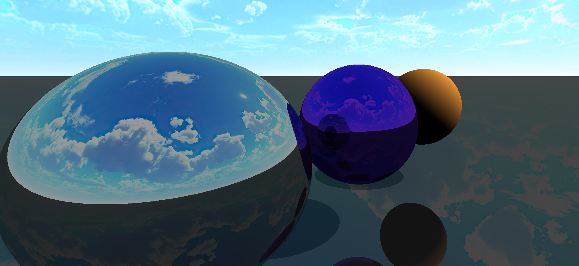
On the screenshot bellow, you can see how the leftmost sphere reflects all colors of light roughly equally, while the middle sphere reflects mostly blue light, this is due to their specular values. You can also see that the sphere on the right has a very low specular value, this means that it will hardly reflect any specular light, but it will reflect a lot of diffuse light, which is the light that is reflected by the albedo channel. To simulate this behavior we simply shoot a ray from the camera and bounce him around the scene until it either hits the sky, runs out of energy (which is lost at each bounce) or reaches a established maximum number of bounces. The color of the pixel is then calculated based on the color of the surface the ray hit and the color of the light that bounced off of it.
Now you may notice that this gives us very nice reflections, however, the shadow on the orange sphere does not look quite as nice, and this is because we are not taking into account the light that is reflected by surrounding objects. Also, currently we only have this perfect reflections where everything looks extra sharp as if all the objects were mirrors, but what if we wanted more smooth reflections? Then our render gets a little more complicated, to realistically calculate the exact light tha is reflected by a point of an object, we have to calculate the equation:
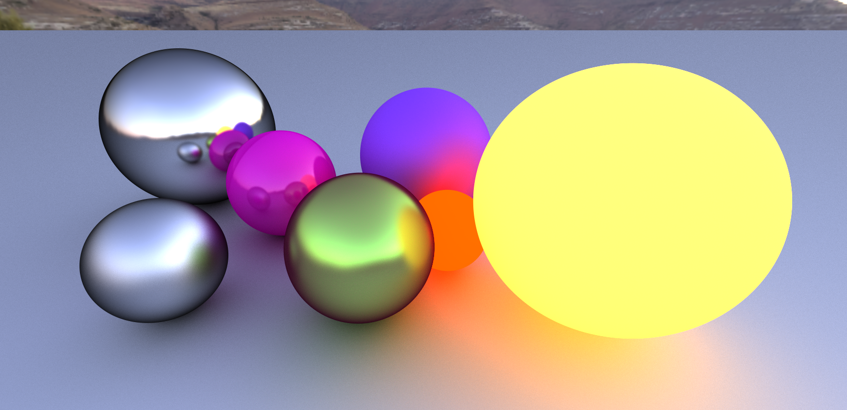
I won't go into too much details because this is not a tutorial nor am I an expert, but the aforementioned article discusses this equation bit by bit. The simple idea is that we have to sum the light that comes from all directions into the point we want to define the color for, to add insult to injury, note that this equation is recursive, which means that we have to calculate the light that comes from all directions, and then calculate the light that comes from all directions of those directions, and so on. This is a very expensive operation and we can't really compute the integral for that, so we use a probabilistic method called Monte Carlo integration to sample the scene in real time. This gives us a noisy image for a while but very quickly it converges to a nice scene with light emissions and photorealistic textures like the image bellow.
The noise effect can be reduced by implementing denoising algorithms, which have been gaining a lot of attention lately. NVIDIA as well as other researchers have been working on this problem and have come up with some very interesting solutions. I will try to implement some of these algorithms in the future, but for now I will leave it at that. I will make sure to include links to the papers and articles discussing these algorithms in the learning resources section.
- GPU Ray Tracing in Unity Part one by David Kuri (web article)
- GPU Path Tracing in Unity Part two by David Kuri (web article)
- GPU Path Tracing in Unity Part three by David Kuri (web article)
- Ray Tracing: How NVIDIA Solved the Impossible! (video)
- Automatic Parameter Control for Metropolis Light Transport (paper)
- Generalized Resampled Importance Sampling: Foundations of ReSTIR (paper)
- Rearchitecting Spatiotemporal Resampling for Production (paper)
🚧 Under construction 🚧
Procedural animation is a very interesting topic, and it is something that I have been wanting to explore for a while. It allows us to control and animate objects in a very natural way, by defining a set of rules that govern the behavior of different segments of the object.
For this project, I based myself on a few resources I could find online. Initially, my goal is to simply control a spider like object and make it walk around, but I will try to expand on this idea and make it more interesting on the future.
This video illustrates the idea I will try to follow. The spider has four limbs, which one with three bones that follow a few rules. To control these bones, we must use something called Inverse Kinematics, which is a technique to move objects based on a pivot, a target point and a pole. The pivot is a point that defines the origin of the limb, the target is used to define the point the limb should reach for, it is where the limb should end if possible and finally the pole define the rules of how the limb will bend. This video: "FK and IK Explained - Which One to Use and When?" helps to understand what is inverse kinematics and how it is different from the more traditional forward kinematics.
To implement inverse kinematics, I based myself on the following video: C# Inverse Kinematics in Unity 🎓. The idea is to iterate over the bones multiple times back and forth, each time we move the bones closer to the desired position and stop once we are close enough or once we reach a maximum number of iterations.
🚧 Under construction 🚧
🚧 Under construction 🚧
