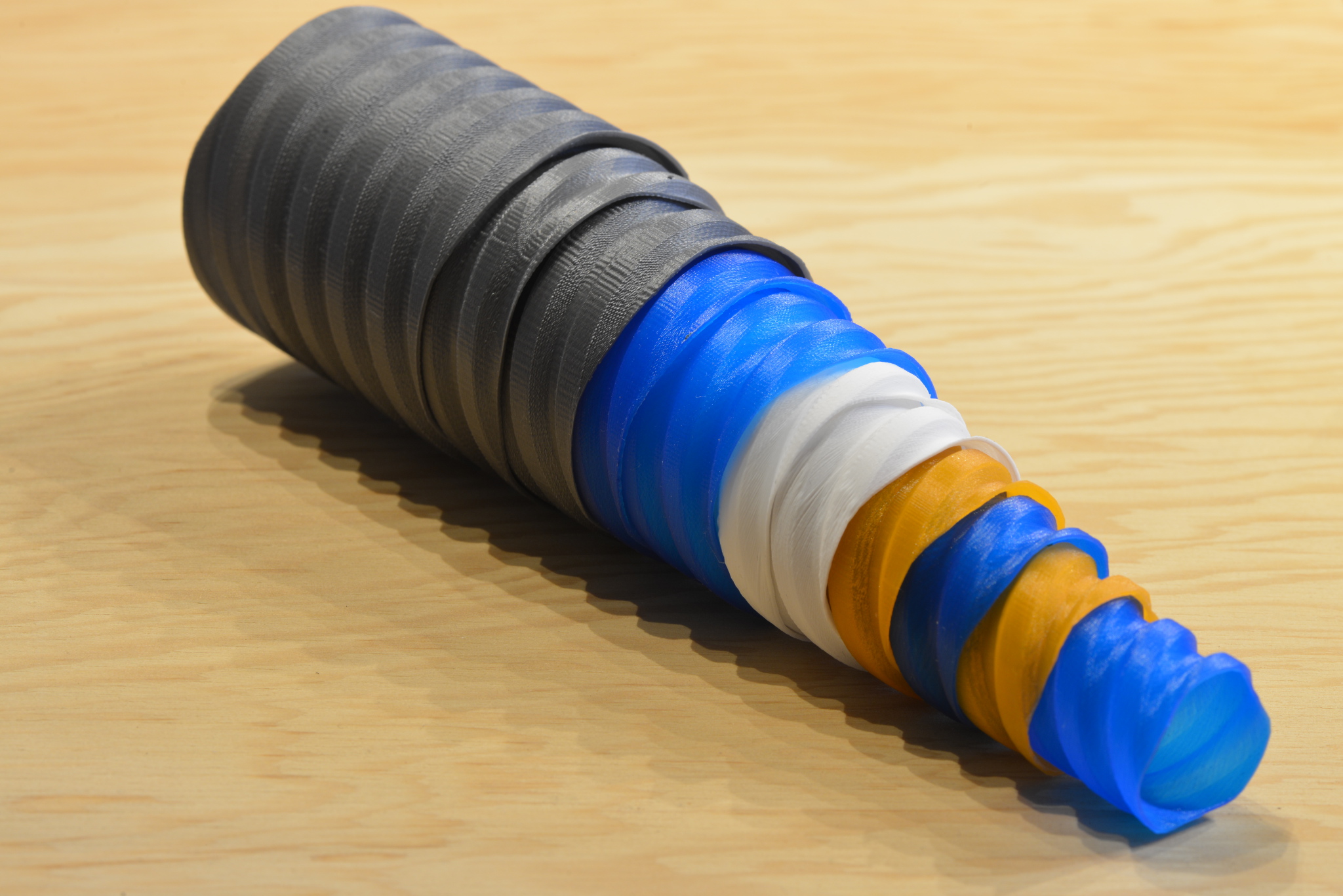
Little aesthetic/artwork kinda stuff. Nice to play with, but don't expect it
to be useful :)
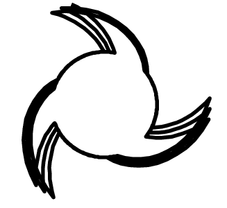
Inspired by shells I have seen
created by Chris K. Palmer:

Printing multiple shells within one print usually means to move the print-head between each layer; moving the print-head creates visible seams between layers.
This program generates GCode directly (no extra slicer needed) in a way that multiple continuous shells are printed on the same printbed in sequence.
Compile it first
$ make
Now you can use it; here a little synopsis that you get if you invoke the program without parameters.
usage: ./multi-shell-extrude [options]
Synopsis:
... Long option          [short]: <help>

[ Screw-data from template ]
    --screw-template <value>[-t]: Template string for screw. (default: 'AABBBAABBBAABBB')
    --thread-depth <value>  [-d]: Depth of thread, initial-size/5 if negative (default: '-1.00')
    --twist <value>             : Twist ratio of angle per radius fraction (good -0.3..0.3) (default: '0.00')

[ Screw-data from polygon file ]
    --polygon-file <value>  [-D]: File describing polygon. Files with x y pairs (default: '')

[ General Parameters ]
    --height <value>        [-h]: Total height to be printed (must set) (default: '-1.00')
    --pitch <value>         [-p]: Millimeter height a full turn takes. Negative for left-turning screw; 0 for straight hull. (default: '30.00')
    --size <value>          [-s]: Polygon sizing parameter. Means radius if from --screw-template, factor for --polygon-file (default: '10.00')
    --center-offset <value>     : Rotation-center offset into polygon. (default: '0.00,0.00')
    --auto-center               : Automatically center around centroid. (default: 'off')
    --pump <value>              : Pump polygon as if the center was not a dot, but a circle of this radius (default: '0.00')
    --number <value>        [-n]: Number of screws to be printed (default: '2')
    --start-offset <value>      : Initial offset for first polygon (default: '0.00')
    --offset <value>        [-R]: Offset increment between screws - the clearance (default: '1.20')
    --lock-offset <value>       : EXPERIMENTAL offset to stop screw at end; Approx value: (offset - shell_thickness)/2 + 0.05 (default: '-1.00')
    --brim <value>              : Add brim of this size on the bottom for better stability (default: '0.00')
    --brim-spiral-factor <value>: Distance between spirals in brim as factor of shell-thickness (default: '0.55')
    --brim-smooth-radius <value>: Smoothing of brim connection to polygon to not get lost in inner details (default: '0.00')
    --vessel                    : Make a vessel with closed bottom (default: 'off')

[ Quality ]
    --layer-height <value>  [-l]: Height of each layer (default: '0.16')
    --shell-thickness <value>   : Thickness of shell (default: '0.80')
    --feed-rate <value>     [-f]: maximum, in mm/s (default: '100.00')
    --layer-time <value>    [-T]: Min time per layer; upper bound for feed-rate (default: '3.00')
    --fan-on-height <value>     : Height to switch on fan (default: '0.30')
    --slender-elephant <value>  : Extrusion multiplier at first two layer heights to prevent elephant foot (default: '0.90')
    --retract <value>           : Millimeter of retract (default: '1.20')
    --first-layer-speed <value> : Feedrate multiplier for first layer (default: '0.70')

[ Printer Parameters ]
    --nozzle-diameter <value>   : Diameter of extruder nozzle (default: '0.40')
    --bed-temp <value>          : Bed temperature. (default: '-1.00')
    --temperature <value>       : Extrusion temperature. (default: '190.00')
    --temperature-variation <value>   : Temperature variation around --temperature, e.g. to get dark lines in wood filament. (default: '0.00')
    --filament-diameter <value> : Diameter of filament (default: '1.75')
    --bed-size <value>      [-L]: x/y size limit of your printbed. (default: '150.00,150.00')
    --head-offset <value>   [-o]: dx/dy offset per print. (default: '45.00,45.00')
    --edge-offset <value>       : Offset from the edge of the bed (bottom left origin). (default: '5.00,5.00')

[ Output Options ]
    --postscript            [-P]: PostScript output instead of GCode output (default: 'off')
    --ps-thick-factor <value>   : Line thickness factor for shell size. Chooser smaller (e.g. 0.1) to better see overlaps (default: '1.00')
    --nested                    : For PostScript: show nested (Matryoshka doll style) (default: 'off')
Some of the long options have short equivalents for convenient short invocations.
Output (GCode or PostScript) is on stdout, so you typically would redirect the output to a file.
See sample invocations below in the Gallery.
Make sure to give the machine limits of your particular machine with
the --bed-size and --head-offset option to get the most screws on your bed.
Each shell is extruded separately in a single spiral ('vase'-like) run, so that
there is no seam between layers. Multiple shells can be printed on the same bed:
each vase is printed to its full height, then the next one is printed next to
it. To avoid physical collisions, they are printed diagonally so that the
printhead does not touch the already printed one (Use the --head-offset option
to configure the needed clearance).
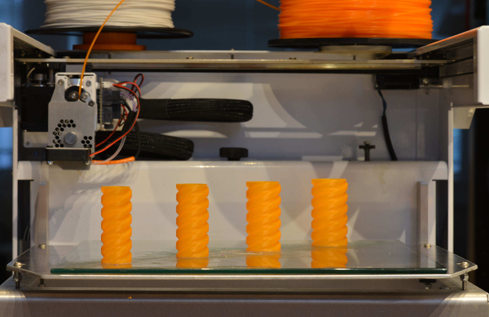 (Type-A Machine Series 1 2014)
The result are shells that can be screwed into each other.
(TODO: describe better)
Template (flag --screw-template or -t) describes the shape. The letters in
that string describe the screw depth for a full turn.
A template AAZZZAAZZZAAZZZ is a screw with three parallel threads,
with 'inner parts' (the one with the lower letter 'A') being 2/3
the width of the outer parts. AAZZZ would have one thread per turn.
The string-length represents a full turn, so AAZZZZZZZZ would
have one narrow thread.
The range of letters (here A..Z) is linearly mapped to the thread
depth.
Try AAZZMMZZZZ. If you only use two letters, then AABBBAABBB
is equivalent to AAZZZAAZZZ
The --twist parameter allows to give things a little twist:
./multi-shell-extrude --pitch=120 --thread-depth=12 --height=60 --twist=0.2 --screw-template=ABABABABAB > twist.gcode
Note, we are giving a relatively high pitch value to manage the overlaps between layers - see below in PostScript output an example.
Alternatively, you can read an arbitrary polygon from a file. The vertices need to be given counterclock wise. The rotation of the resulting screw will be around the origin. The polygon file is very simple: each line contins an x and y coordinate, As an example, see sample/hilbert.poly. You can create polygon files by hand or with a program. Often it is simple to manually (editor, sed, awk) extract polygon data from from sources such as SVGs.
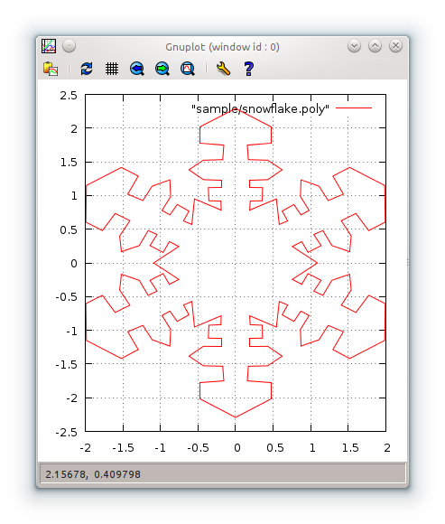
Pro-tip: you can use gnuplot to visualize polygons while you are working on them.
 $ gnuplot
         G N U P L O T
         Version 4.6 patchlevel 4    last modified 2013-10-02
 gnuplot> plot "sample/snowflake.poly" with lines
 gnuplot>
While playing with the options, it is nicer to first look at how it would look
on the printbed. So there is the option -P (or --postscript) to output
postscript instead of GCode. If you use a PostScript viewer such as okular
that re-loads the content whenever the file changes, you can play with the
options and see how things change.
The first three layers of the spiral are shown, which gives an
indication if the filament would stick - if the rotation is too quick, you see
separate overlapping lines. The thickness of the shell is roughly represented
by the thickness of the line in the postscript output.
 $ ./multi-shell-extrude --height=5 -P > out.ps
 $ okular out.ps &    # start postscript viewer
 # now play around with the options and watch the changes. In the following
 # example, we set the pitch too steep, so we see overlaps
 $ ./multi-shell-extrude -n 1 --pitch=10 --height=5 --thread-depth=10 --twist=0.3 -t BAAAABAAAABAAAA -P > out.ps
We deliberately chose a very steep pitch here (--pitch; here full turn in
10mm).
The layers of the 3D print now already miss the corresponding previous
layer -- they are not overlapping sufficiently anymore. We can see this in the
following PostScript output, so we don't mess up a 3D print.
To fix, either increase pitch -p (or --pitch) (number of mm height for a
full turn) or decrease layer-height -l (--layer-height)
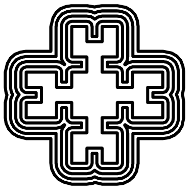
The usual view displays exactly the layout on the print-bed with all screws spread out.
If you want to see how the screws nest, add the --nested parameter
then they are all shown centered around one point:
./multi-shell-extrude -n 5 --height=10 --pitch=180 --size=3.5 --polygon-file=sample/hilbert.poly -P --nested > out.ps
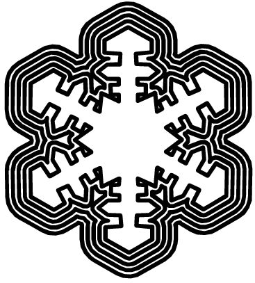
./multi-shell-extrude -n 5 --height=10 --pitch=180 --size=10 --polygon-file sample/snowflake.poly -P --nested > out.ps
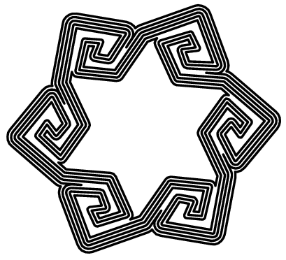
Spiral star 6, six of them. With size point six. Starting at offset -2:
./multi-shell-extrude --polygon-file sample/SpiralStar6.poly -h 10 -n 6 --start-offset=-2 --size 0.6 -p 0 --nested -P > out.ps
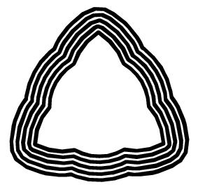
Here a regular screw, 5 nested into each other:
./multi-shell-extrude -n 5 --height=10 --pitch=180 --size=10 --thread-depth=5 -t aaabaaabaaab -P --nested > out.ps
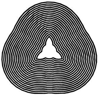
.. how about 20 nested screws ?
./multi-shell-extrude -n 20 --height=10 --pitch=180 --size=5 --thread-depth=5 -t aaabaaabaaab -P --nested > out.ps
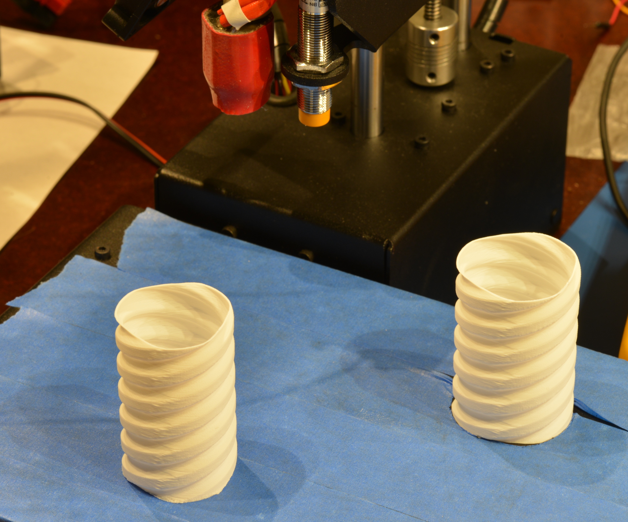
This result was created with this commandline:
./multi-shell-extrude --layer-height=0.12 --thread-depth=2 --size=10 --offset=1.5 -n 4 --height=60 --bed-size=305,305 --head-offset=50,50 > out.gcode
Printed twice with different filaments.
./multi-shell-extrude --layer-height=0.12 --thread-depth=2 --size=16 --offset=1.5 -n 2 --height=60 --bed-size=150,150 --head-offset=50,50 > /tmp/screw-printrbot.gcode
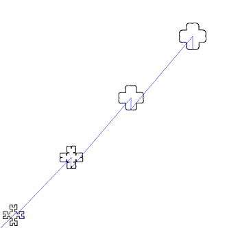
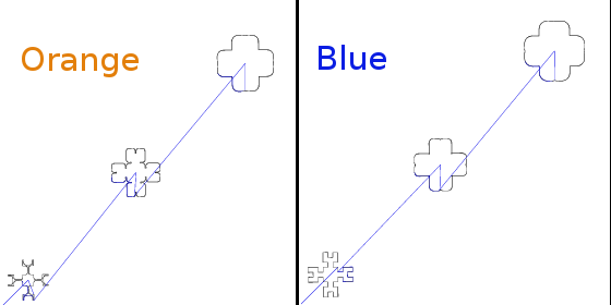
Here, we generate two different colors in two prints. We want to print the
hilbert example from the sample/ directory. The shells should be 1.2mm apart.
We want them alternating in color, so we do to prints with different colors
with each 2.4mm apart. For that, we give both the shell increment value
--offset 2.4, but with different start values with the --start-offset option.
The blue print starts with --start-offset=0, so no initial offset. The
orange print starts with --start-offset=-1.2 (yes you can give negative values, then a polygon is constructed that fits on the inside).
Now orange prints the offsets [ -1.2mm, 1.2mm, 3.6mm ], while blue prints [ 0mm, 2.4mm, 4.8mm ].
In general, to spread over multiple prints, you can use the initial shell value
--start-offset together with the offset increment --offset to generate the
right offsets.
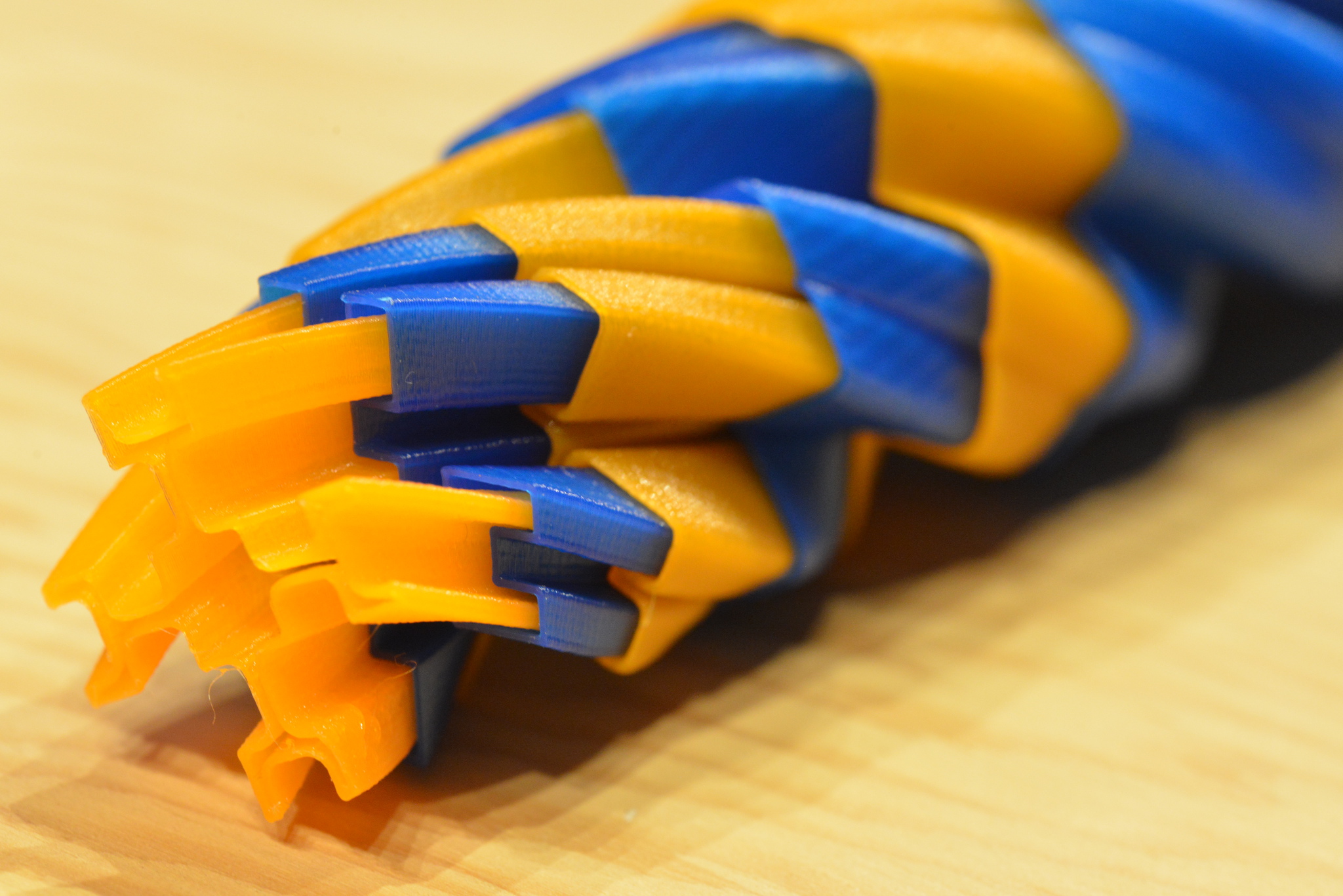
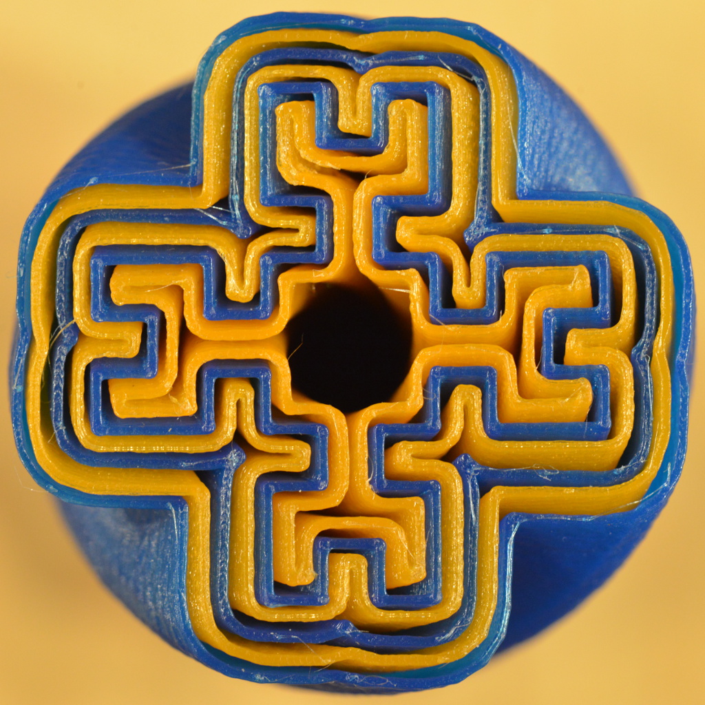
The resulting screws nest together nicely with 1.2mm distance:
 ./multi-shell-extrude -n 3 --start-offset=-1.2 --offset=2.4 --height=60 --pitch=180 --size=3.5 --polygon-file sample/hilbert.poly --bed-size=220,220 > /tmp/orange.gcode
 ./multi-shell-extrude -n 3 --start-offset=0    --offset=2.4 --height=60 --pitch=180 --size=3.5 --polygon-file sample/hilbert.poly --bed-size=220,220 > /tmp/blue.gcode
The diagonal collision avoidance is a bit simplistic and wasting space. Might not be enough for printers with small build volume. Model the print-head and gantry and configuration to make a more compact staggered print.
