Raspberry Pi Pico is a new low-cost, high-performance microcontroller board with flexible digital interfaces. A Microcontroller is a compact integrated circuit designed to govern a specific operation in an embedded system. You don’t use monitors or keyboards, but program them to take their input from, and send their output to the input/output pins. Using these programmable connections, you can light lights, make noises, send text to screens, and much more.
A Raspberry Pi Pico has GPIO pins, much like a Raspberry Pi computer, which means it can be used to control and receive input from a variety of electronic devices.

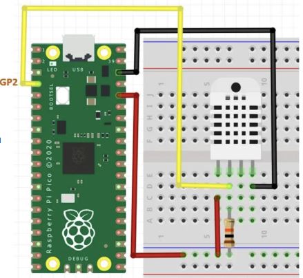
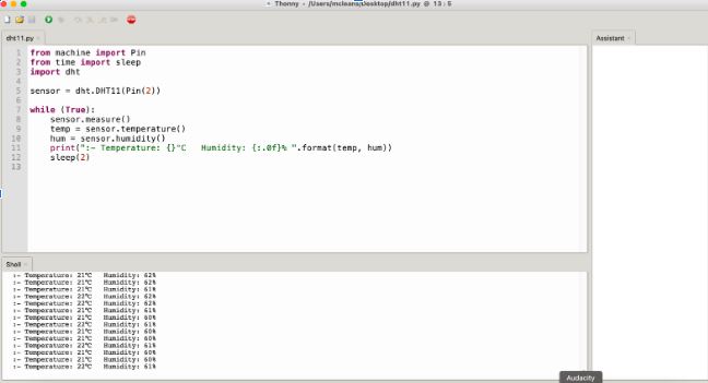
We are going to use Raspberry Pi Pico and a sensor to read temperature and humidity values in our room.
MicroPython is a full implementation of the Python 3 programming language that runs directly on embedded hardware like Raspberry Pi Pico. You get an interactive prompt (the REPL) to execute commands immediately via USB Serial, and a built-in filesystem. The Pico port of MicroPython includes modules for accessing low-level chip-specific hardware.
We will learn how to use the beginner-friendly language MicroPython to write programs and connect hardware to make your Raspberry Pi Pico interact with the world around it. Using these skills, you can create your own electro‑mechanical projects, whether for fun or to make your life easier.
- MicroPython firmware for Raspberry Pi Pico
- The Thonny Python IDE
- A Raspberry Pi Pico with soldered headers
- A computer that can run the Thonny IDE and program a Raspberry Pi Pico
- A micro USB cable
- A breadboard and M-M jumper leads for connecting additional components (optional)
We are going to learn :
- How to load the MicroPython firmware onto a Raspberry Pi Pico
- How to program a Raspberry Pi Pico using MicroPython
- How to connect additional components to a Raspberry Pi Pico and write MicroPython programs to interact with them
- Click here to download micropython UF2 file for the board.
- Hold the BOOTSEL button on your Raspberry Pi Pico and connect your pico to your computer via USB (Do not release the button)
- Release the button after pico is connected
- It will mount as a Mass Storage Device called RPI-RP2.
- Drag and drop the MicroPython UF2 file onto the RPI-RP2 volume. Your Pico will reboot. You are now running MicroPython.
- You can access the REPL via USB Serial.
Thonny is an integrated development environment (IDE) for Python that is designed for beginners. It supports different ways of stepping through the code, step-by-step expression evaluation, detailed visualization of the call stack and a mode for explaining the concepts of references and heap.
An IDE is software that gives its users an environment for performing programming, along with development as well as testing and debugging the application.
- Click here to download the IDE version for your specific operating system.
- If you are on linux use the commands below to install Thonny:
sudo apt install python3 python3-pip python3-tkbash <(wget -O - https://thonny.org/installer-for-linux)
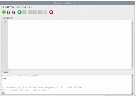
When opening Thonny for the first time, select Standard Mode. For some versions this choice will be made via a popup when you first open Thonny. However for the Raspberry Pi release you should click on the text in the top right of the window to switch to Regular Mode. Make sure your Raspberry Pi Pico is plugged into your computer and click on the word Python followed by a version number at the bottom-right of the Thonny window — this is the Python interpreter that Thonny is currently using. Normally the interpreter is the copy of Python running on Raspberry Pi, but it needs to be changed in order to run your programs in MicroPython on your Pico, clicking the current interpreter will open a drop down.
Go to run > Select interpreter > Select Micropython (Raspberry Pi Pico) as shown
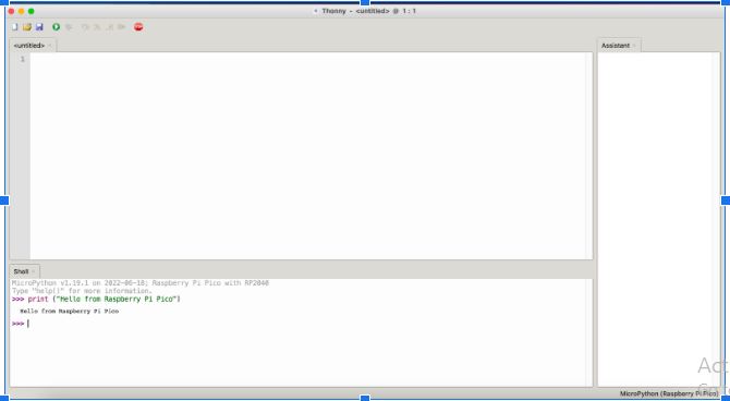
You can now access the REPL (read–eval–print loop) from the Shell panel, try and print out a string as shown below.
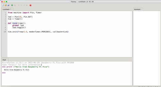
MicroPython adds hardware-specific modules, such as machine, that you can use to program your Raspberry Pi Pico.
Let’s create a machine.Pin object to correspond with the onboard LED, which can be accessed using GPIO pin 25.
You can use the Timer module to set a timer that runs a function at regular intervals
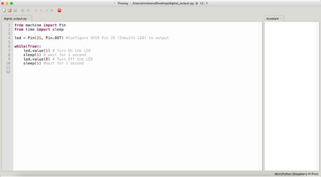
If you set the value of the LED to 1, it turns on and setting it to 0 turns it off.
Enter the following code, make sure you tap Enter after each line
- First save the project on your computer as a “.py” file e.g
blinky.py. Tip You need to enter the.pyfile extension so that Thonny recognises the file as a Python file. - Navigate to File >> Save
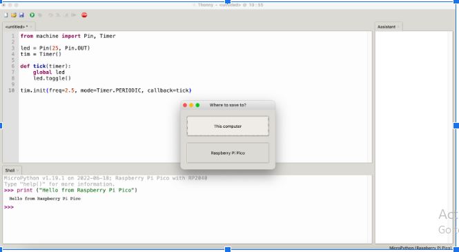
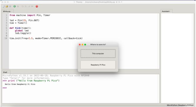
- Select “This computer” and save
- To save the file onto your Raspberry Pi Pico
- Navigate to File >> Save As
- Select “Raspberry Pi Pico” this time.
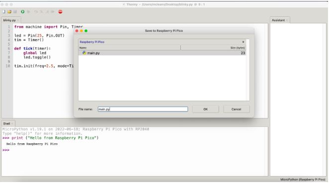
Note In order for your program to be executed every time the Pico starts your program has to be saved as “main.py”
- Click OK
- Remove power from the Pico. When the Pico is powered again the program starts executing automatically.
Congratulations your Pico is now running Blinky
Digital Input and Output is a very useful concept in microcontrollers. It enables the microcontroller to output digital signals to the world and also receive digital signals.
In the example project in the first section we implemented a digital output program.
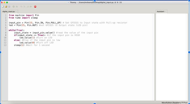
In order to detect an input signal we have to configure the “Pin” as an input and then read its value. We get a “True” value when the pin is HIGH and a “False” value when the pin is LOW.
We can then use this signal to turn ON and OFF the onboard LED
Analog input pins enable the microcontroller to read continuously changing signals such as sensor data from sensors that produce an analog output. In this example we will connect an analog sensor to an analog pin of the microcontroller and read values from it.
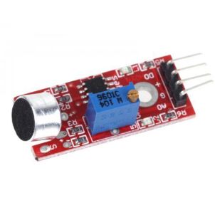
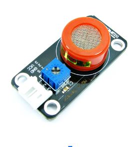
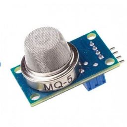
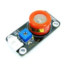
Each team has at least one on the sensors listed below
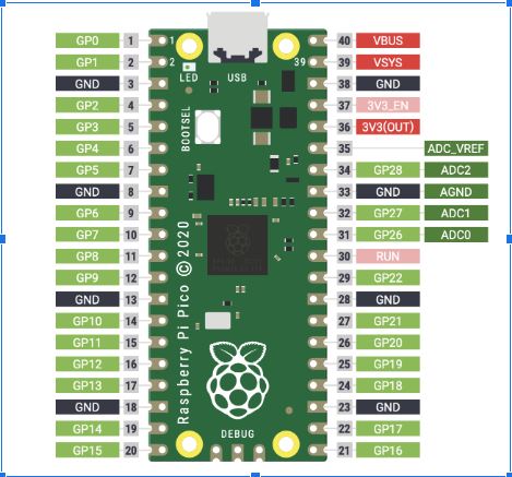
- Connect the sensor’s Vcc pin to the 3V3(OUT) pin on your Pico.
- Connect the sensor’s GND pin to the AGND pin of your Pico
- Connect the sensors DO/Out pin to GPIO26 of your Pico
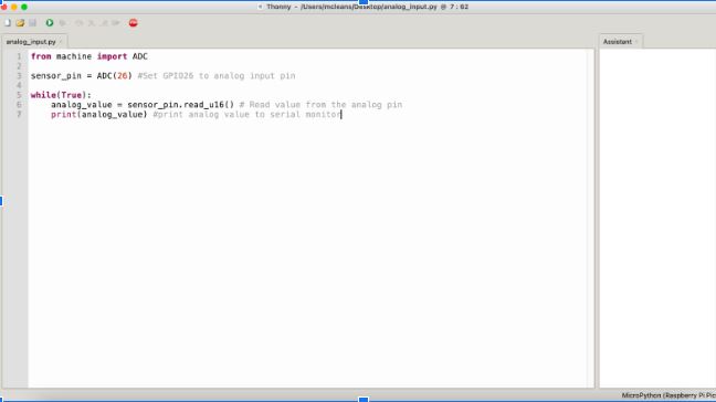
Use the program below to read the raw sensor analog values using your Pico.
The received analog value is a 16 bit value ranging between (0 - 65535). This value can be used to calibrate the sensor
