Simple Toolchain around the Simple As Possible Ben Eater computer architecure, including a VM ( emulator ), assembler, compiler, decompiler.
This Project is for learning purpose, in fact we are trying to build a toolchain around the famous SAP (Simple-As-Possible) ben eater computer architecture.
Ben Eater Simple as Possible Architecture
- Ben Eater Machine
- Overview
- Ben Eater Computer Emualtor Design
- How everything works together
- Instruction Set
- Modules
- Compiling
- Executing
Architecture of physical machine
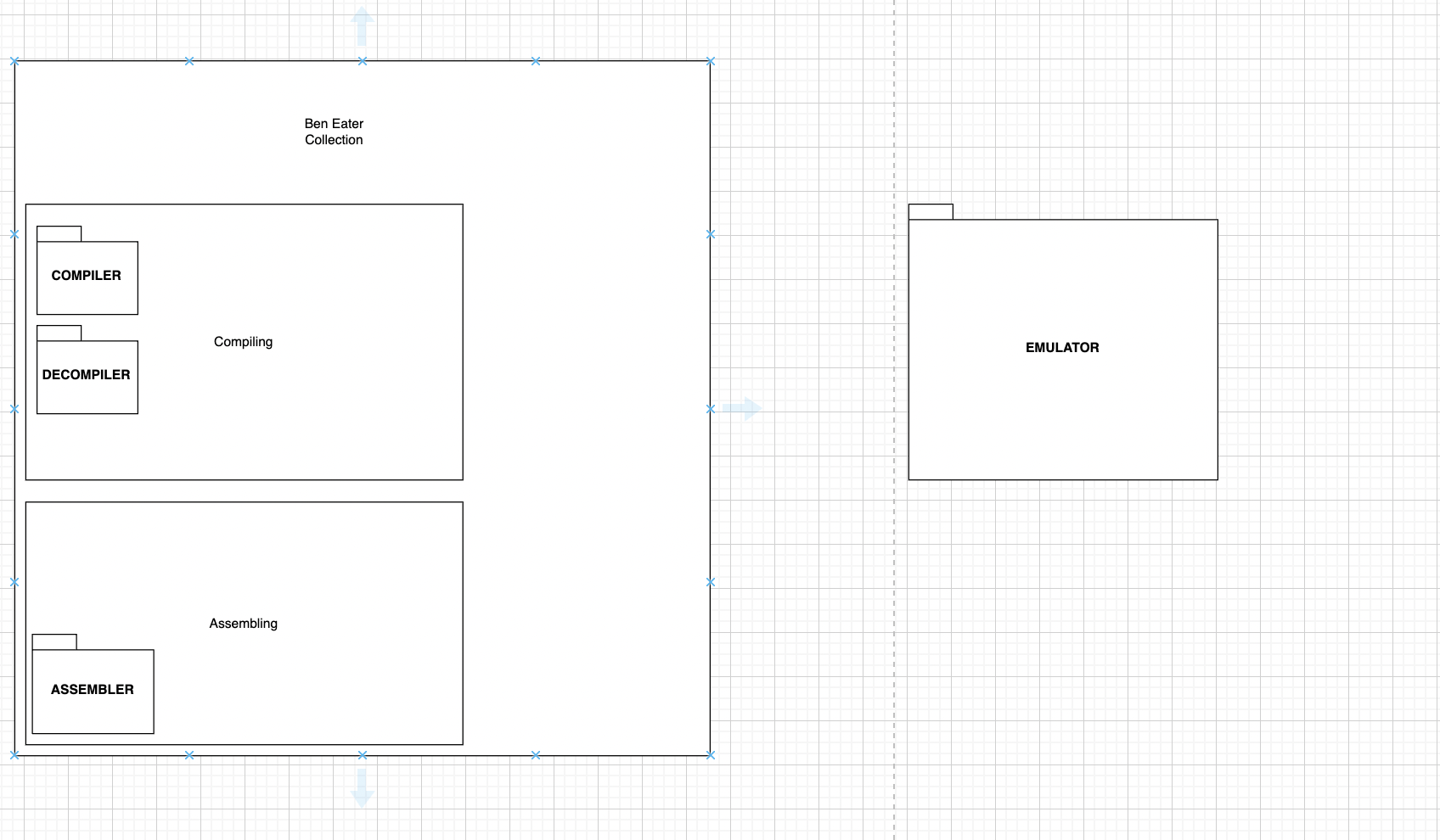
The Design is pretty simple, and will include 3 modules.
- Ben Eater Computer Emulator
- Assembler
- Compiler
- Decompiler
This module will produce a ( VM ) Virtual Machine, which is actually an emualtor of the ben Eater computer, so will execute the instruction set of the physical device.
This module will produce a system software that translates a higher level human readable code into machine code.
This module will produce a system software that will compile a higher level human readable code, more structured, into assembly language.
This module will produce a system software that will reverse an assembly file into an higher level language.
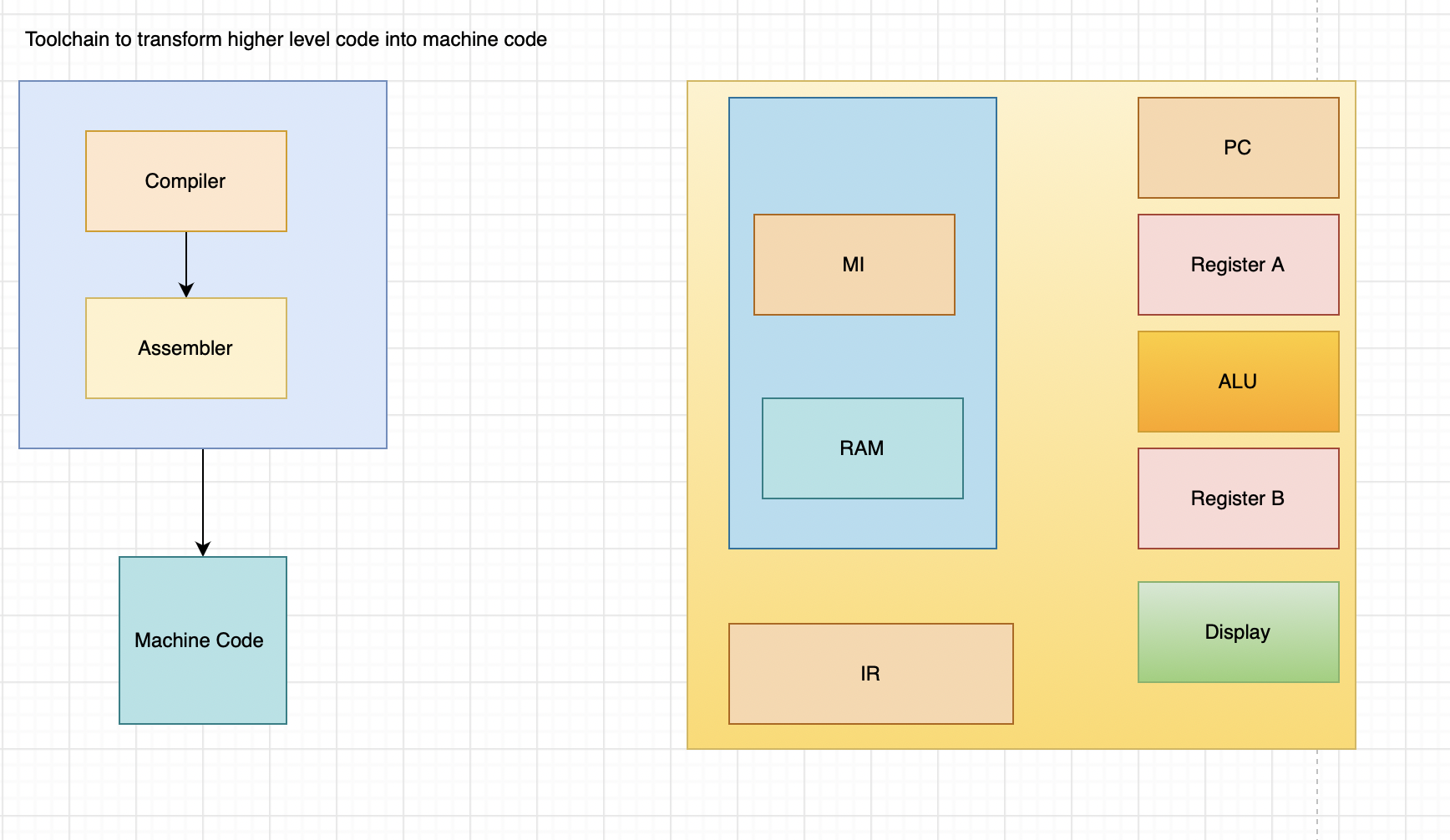
Let's start with registers, the architecture features three registers, named, Register A, Register B, Register IR
So in this simple design we have two general purposes registers.
- Register A
- Register B
In this architecture we have special registers as well:
- Program Counter PC ( Holds the address of next instruction to be executed )
- Memory Address Register MI ( holds the the address of main memory )
- Instruction Register IR ( holds the current instruction that's being executed)
And we have a special purpose register, specifically the IR register will hold the current instruction that's being executed.
The RAM, stores the program currently the computer is executing and the data. The computer uses 4-bit addresses which means it will only have 16 bytes of RAM, limiting the size and complexity of programs it can run. This is by far its biggest limitation.
The program counter (PC) counts in binary to keep track of which instruction the computer is currently executing
The arithmetic logic unit (ALU) part of a CPU is usually capable of performing various arithmetic, bitwise, and comparison operations on binary numbers. In our simple breadboard CPU, the ALU is just able to add and subtract. It’s connected to the A and B registers and outputs either the sum of A+B or the difference of A-B.
Instructions are 8 bit long, and include.
- NOP => 0x00
- LDA => 0b0001 @ address[3:0]
- ADD => 0b0010 @ address[3:0]
- SUB => 0b0011 @ address[3:0]
- STA => 0b0100 @ address[3:0]
- OUT => 0b0000
- JMP => 0b0110 @ address[3:0]
- LDI => 0b0111 @ value[3:0]
- JC => 0b1000 @ address[3:0]
- JNC => 0b1001 @ address[3:0]
- HALT => 0b1111 @ 0b0000
As said before we have 4 modules, the VM ( emulator ), the Assembler, the Compiler, and the Decompiler.
We will split the into 2 groups:
- Compiling ( Assembler, Compiler, Decompiler)
- Executing ( Emulator )
Compiling Module will have all submodules that enable us to write code in a higher level human readable manner.
Executing Modules is simpler, will have one submodule for now, and will execute the code that is compliant with the instruction set.
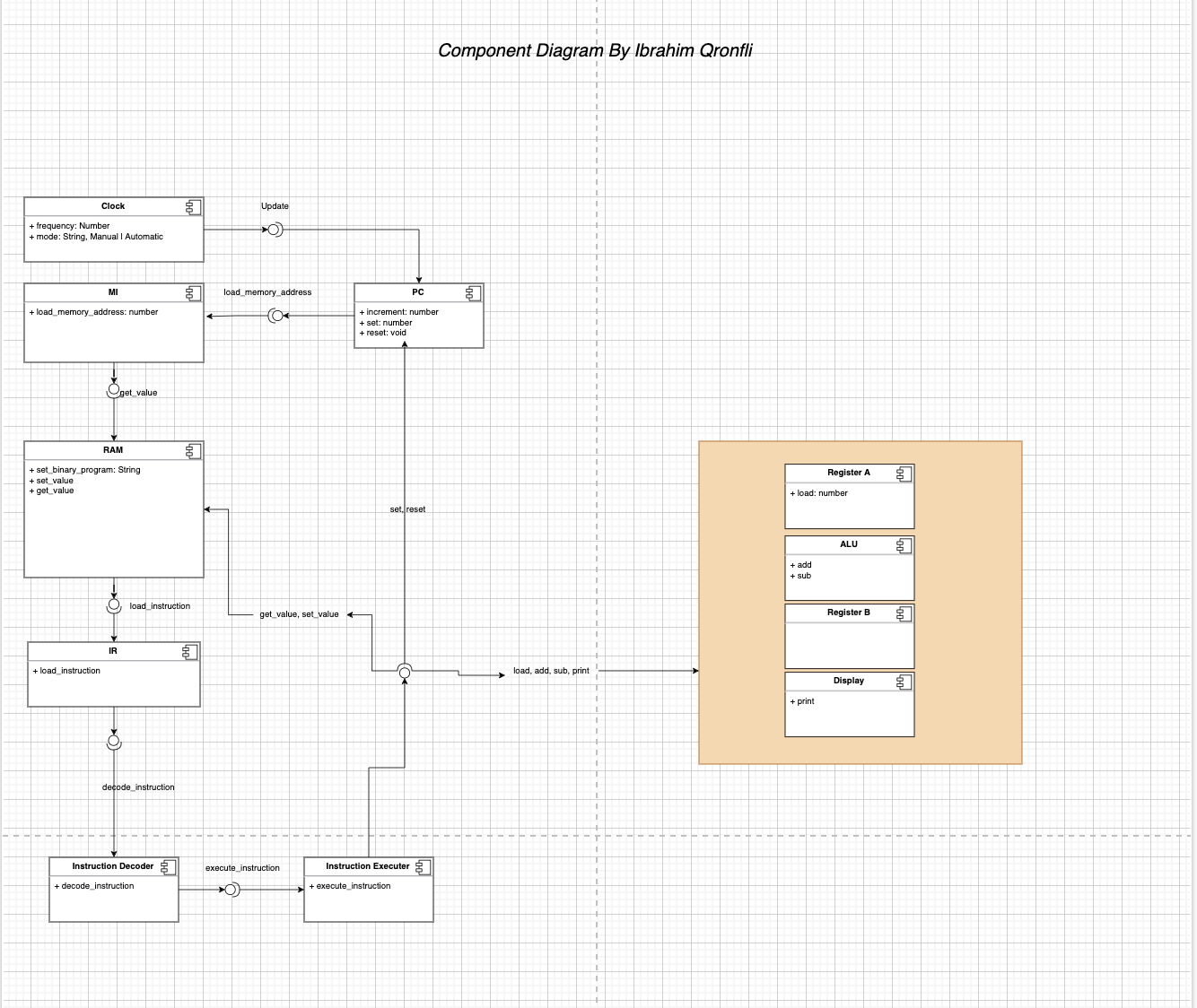
Here we have a simple UML componente diagram UML component diagram draw.io version
LDI 12
OUT
STA 14
LDI 3
OUT
LDA 14
OUT
LDI 15
STA 15
LDI 1
STA 14
LDA 15
SUB 14
OUT
JC 4
LDI 10
STA 14
LDI 2
STA 15
LDI 0
ADD 15
OUT
JMP 5
LDI 0
STA 13
LDI 2
STA 15
LDI 10
STA 14
LDA 13
ADD 15
OUT
STA 13
LDA 14
SUB 13
JC 6
LDI 1
STA 13
LDI 0
STA 14
LDA 13
STA 15
ADD 14
OUT
STA 13
LDA 15
STA 14
JMP 4
- program => declaration* EOF;
- declaration => varDecl | statement;
- varDecl => "var" IDENTIFIER "=" expression ";";
- statement => exprStmt | printStmt;
- exprStmt => expression ";";
- printStmt => "print" expression ";"
- expression => assignment;
- assignment => (call "." )? IDENTIFIER "=" assignment | equality;
- equality => comparison ( ("!=" | "==") comparison)*;
- comparison => term ( (">" | ">=" | "<" ) term)*;
- term => primary ( ("-" | "+") primary )*
- primary => NUMBER | STRING | "true" | "false" | "nil" | "(" expression ")" | IDENTIFIER;
print(10+20); var me = 100;
will be parsed producing this ast.
first declaration:
PrintDecl { argument: BinaryExpr { operator: Token { token_type: Plus, lexeme: "+" }, right: Literal { value: 20 }, left: Literal { value: 10 } } }
second declaration:
declaration: VarDecl { identifier: "me", initializer: Literal { value: 100 } }


