A Digital Frequency Generator using an Arduino Nano and an AD9833 Module.
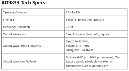
This is a quick and easy project to build a 0 - 12.5MHz digital frequency generator!
Features
- Uses a DollaTek AD9833 (+ MCP41010) module (SPI bus).
- Sine, square and triangle wave generation.
- Frequency range 0 - 1.0MHz square and sine waves (software limited for sine waves) - P2 sketch.
- Frequency range 0 - 1.0MHz (square waves) and 0 - 12.5MHz (sine waves) - P3 sketch.
- Frequency range 0 - 1.0MHz (square and triangle waves) and 0 - 12.5MHz (sine waves) - P4 sketch.
- Raw and amplified (with gain control) wave outputs.
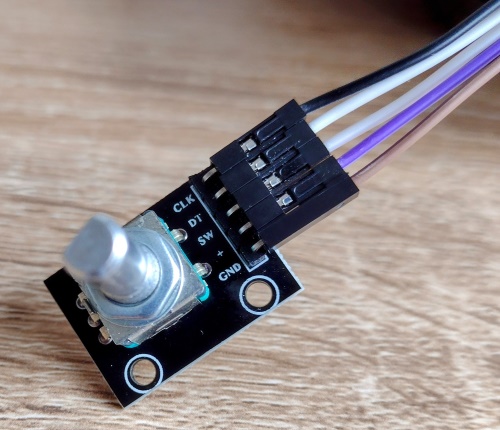
- Full control via a KY-040 rotary encoder.
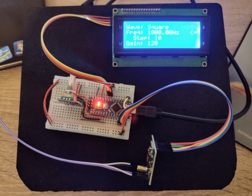
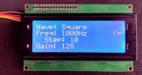
- At a glance settings all on a 20 column x 4 line LCD display (I2C bus).
- Uses open source Arduino libraries for all the hardware modules.
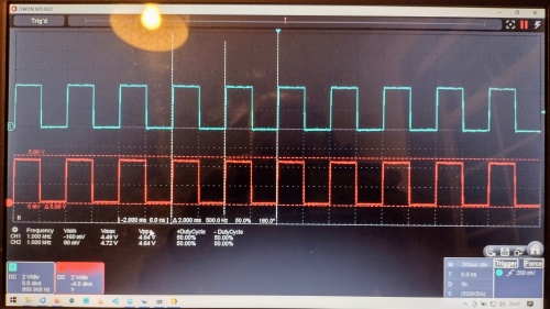
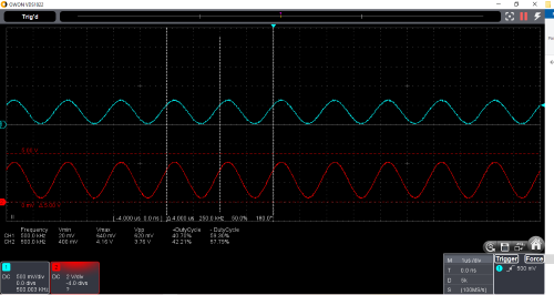
Blue trace: Raw AD9833 output / Red trace: Amplified output
- Turn the knob to inc/dec either the frequency or the gain.
- Button long press to toggle frequency or gain control mode.
- Button double-click to cycle through sine, square and triangle wave output.
- Button single click to change the freqency inc/dec step (freq mode).
- Button single click to change the gain low/mid/high setting (gain mode).
FreqGenADMCP-P1.ino
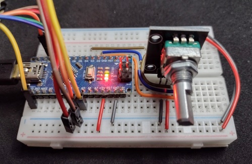
Halfway stage: Just the Rotary Encoder and the LCD modules are active.
This is shown in the accompanying YouTube video (link below).
FreqGenADMCP-P2.ino
Complete: The DollaTek AD9833 and MCP41010 module is also active.
This is shown in the accompanying YouTube video (link below).
FreqGenADMCP-P3.ino
Update 1: The DollaTek AD9833 and MCP41010 module with up to 1.0MHz square and 12.5MHz sine waves.
This update was completed after the YouTube video was made.
FreqGenADMCP-P4.ino
Update 2: The DollaTek AD9833 and MCP41010 module with up to 1.0MHz square and triangle waves, and 12.5MHz sine waves.
This update was completed after the YouTube video was made.
-
Arduino Nano (my go-to Arduino board for quick projects).
-
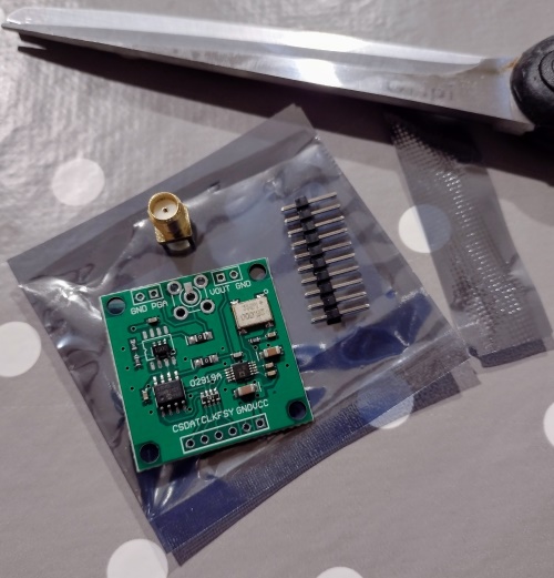
DollaTek AD9833 frequency generator module with onboard MCP41010 and AD8051 op-amp.
-
KY-040 rotary encoder module.
-
HD44780 based 20x4 LCD display.
-
HW-061 I2C to HD44780 piggyback module.
-
Owon VDS1022i USB oscillosope with open source software.
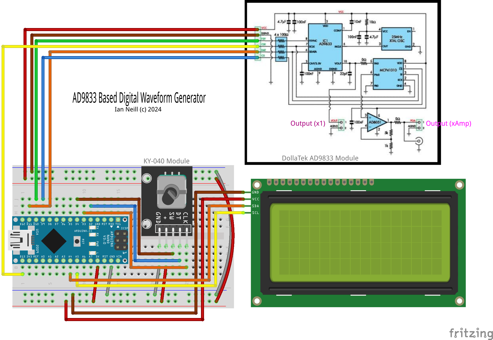
WaveGenAD9833v3.fzz
Blue trace: Raw AD9833 output / Red trace: Amplified output
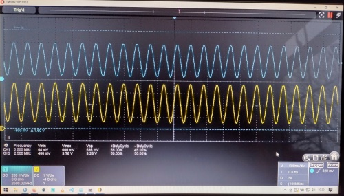
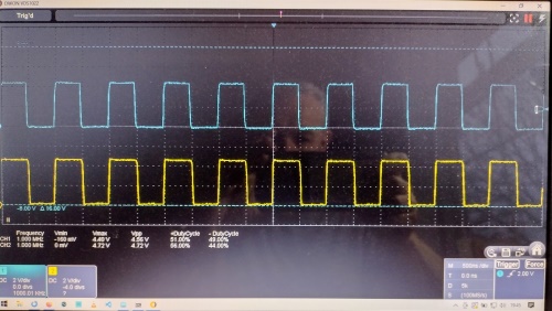
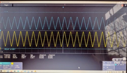
Blue trace: Raw AD9833 output / Yellow trace: Amplified output
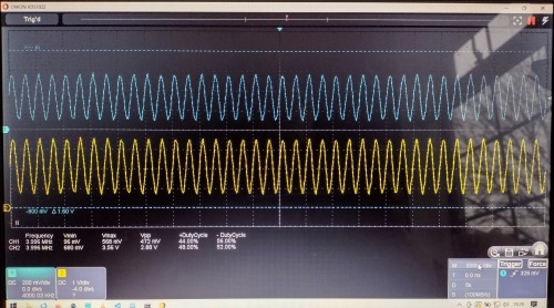
Blue trace: Raw AD9833 output / Yello trace: Amplified output
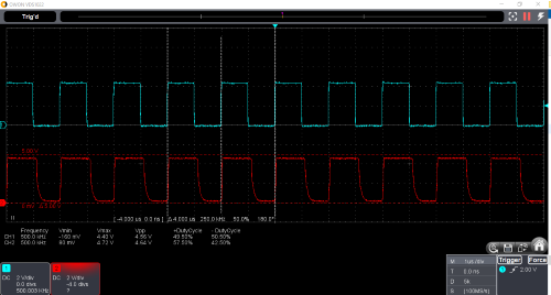
Blue trace: Raw AD9833 output / Red trace: Amplified output
Blue trace: Raw AD9833 output / Yellow trace: Amplified output
Blue trace: Raw AD9833 output / Yellow trace: Amplified output
My project build, code explanation (P1 and P2 sketches) and demonstration on an Owon VDS1022i oscilloscope here:
