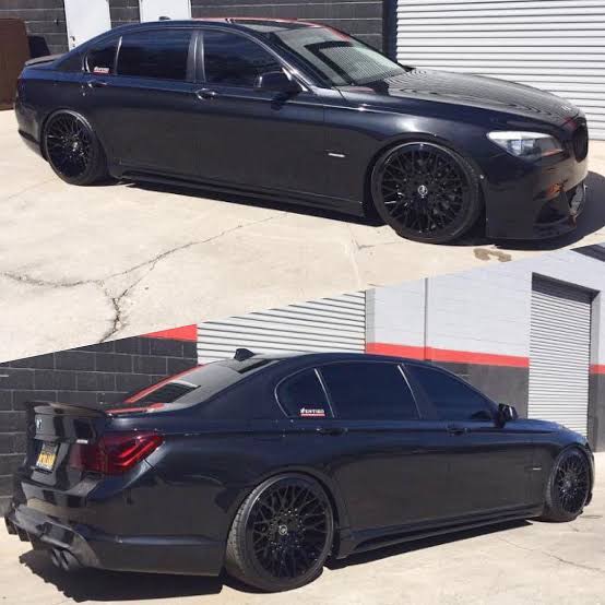
Installing a Ford Falcon Barra engine into a 2009 BMW F01 7 Series 730D.
Arduino Script in main folder, CAN Data in logs folder.
Using a dual CAN interface to recieve data from both the Barra CANbus and the BMW CANbus, and to transfer it between the buses. The two buses are to be isolated from each other, with data being transferred via the interface.
- Decode Barra CAN Messages & Convert for BMW Cluster
Implement checksum algo and counter for BMW data bytes 0 and 1 for sent messages- Decode BMW DME CAN Messages that need to be emulated
emulator almost finished - Malfunction Indicator Lamps from Barra PCM > BMW cluster
- Set Vehicle Speed Source to be
ABS via CANin Barra PCM - 6HP26 TCM can provide speed source to PCM. - Emulate CAN Message for Vehicle Speed Source input on CAN ID 0x4B0 (Emulating the Falcon ABS Module using the BMW ABS Data)
- What is needed to get BMW factory ABS functional?
- Emulate missing DME CAN messages due to removal of DME & TCM modules
- Disable Passive Anti-theft System in Barra PCM
- Fit a second OBD port for Barra PCM diagnostics (4 GND, 5 GND, 16 12V, 6 CAN H, 14 CAN L, FEPS Pin 13)
Wiring Harness finished - Install interface board into vehicle
- Throttle / Accelerator pedal input into PCM
BMW Accelerator pedal should function with Barra PCM - HVAC and compressor control needs to be thought out
BMW Compressor mounted on Barra with custom mounts, controlled by factory HVAC - Brake Status input into PCM
- Cruise control neede to be thought out >
Auto Electrician - BMW shifter to run Ford 6HP26
Gear Selector should function wired up to Ford 6HP26 Transmission - Engine Start/Stop Button >
Auto Electrician - Tyre/Wheel/final drive needs to be set in PCM
Deutche plug kit to make up adaptor wiring harness for accelerator pedal assembly
PCMTECFor programming and configuring the Barra Powertraim Control Module.FORscanFor diagnostics and fault finding.Arduino IDEFor flashing the microcontroller used as the CAN interface.Sublime TextMy preferred text editor for coding.PuttyUsed to SSH into the Raspberry Pi and and sniff CAN DataSocketCANUsed to pull raw CAN data from the vehicle.Libreoffice CalcInterpreting CAN data
- Raspberry Pi 4 with PiCAN3 hat
- Longan Labs CANbed development board
- OBD power isolator & various adaptors
- Multimeter
- J2534 Tool
Pulling Data from the car with a Raspberry Pi + SPI-MCP2515, wired up to PT-CAN_1 at Kombi connector, powered via OBD port


Isolating individual ECUs to determine CAN frame origin by pulling ECU power fuses.
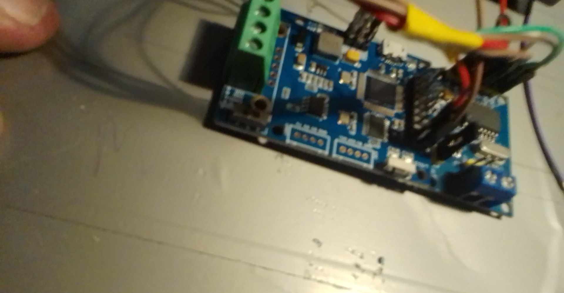
Prototype interface board
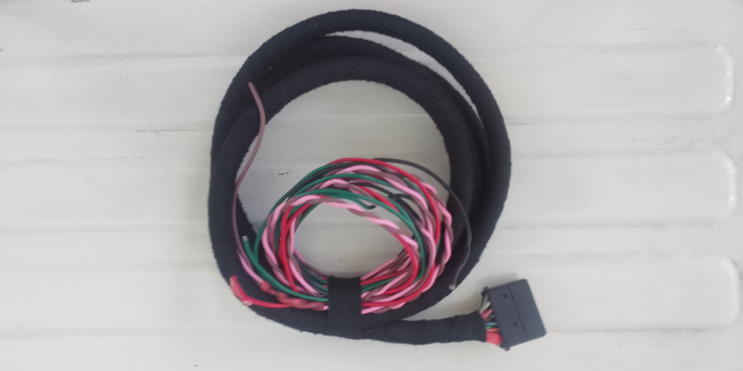
2nd OBD port wiring harness ready to be installed, with FEPS wiring and CAN High, CAN Low to enable diagnostics and programming of the barra PCM.

Each CAN Message that is sent out onto the PT-CAN contains both a checksum and a counter byte, the checksum is at byte[0] and the counter is byte [1].
Here we are emulating the BMW checksum and counter byte on socketcan virtual interface. This has now been implemented into the Arduino code using a CRC8 checksum calculation.

Wiring the Kombi up to 12 Volts power, Ground and PT-CAN Hi & Low.

FG Falcon Git Repo
Notes on Stand Alone PCM Setup
Notes on ABS Module config
BMW Kombi Pin out
Original ECU HSCAN Interface by Mitchell H
Relevant BMW and Ford documents are in the Docs folder.


