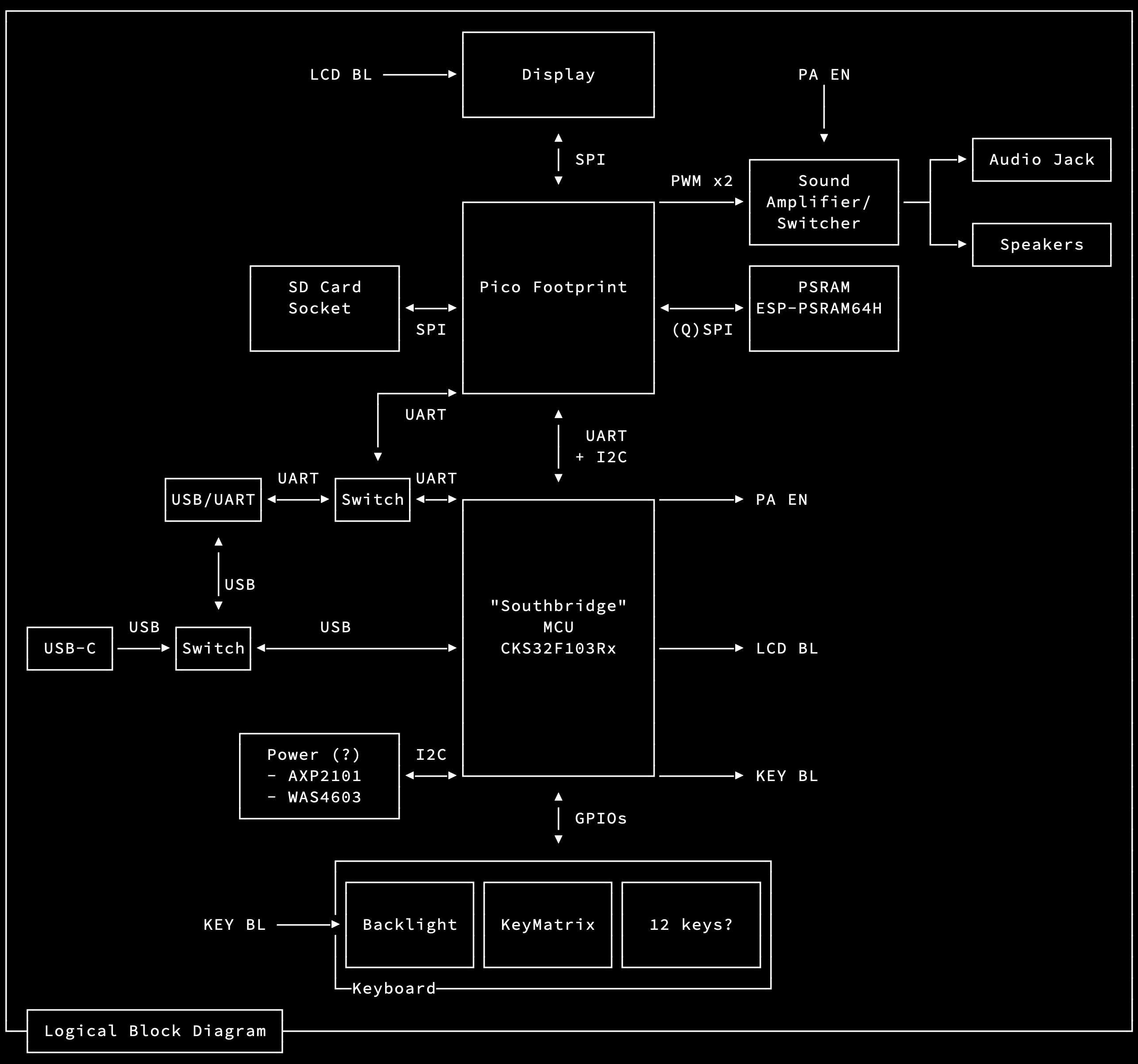
James' Q2 2025 explorations of the pico calc
| Pico Pin # | RP2040 Pad Name | PicoCalc Net | Group | Expansion? | Note |
|---|---|---|---|---|---|
| 01 | GPIO00 | UART0_TX | USB DBG UART | J702-3 | TOP LEFT, USB SIDE |
| 02 | GPIO01 | UART0_RX | USB DBG UART | J702-2 | |
| 03 | GND | GND | - | - | |
| 04 | GPIO02 | RAM_TX | PSRAM | J703-2 | SPI0 |
| 05 | GPIO03 | RAM_RX | PSRAM | J703-3 | SPI0 |
| 06 | GPIO04 | RAM_I02 | PSRAM | J703-4 | SPI0 |
| 07 | GPIO05 | RAM_IO3 | PSRAM | J703-5 | SPI0 |
| 08 | GND | GND | - | - | |
| 09 | GPIO06 | I2C1_SDA | SOUTHBRIDGE | - | I2C1 |
| 10 | GPIO07 | I2C1_SCL | SOUTHBRIDGE | - | I2C1 |
| 11 | GPIO08 | UART1_TX | SOUTHBRIDGE | - | UART1 |
| 12 | GPIO09 | UART1_RX | SOUTHBRIDGE | - | UART1 |
| 13 | GND | GND | - | - | |
| 14 | GPIO10 | SPI1_SCK | LCD | - | SPI1 |
| 15 | GPIO11 | SPI1_TX | LCD | - | SPI1 |
| 16 | GPIO12 | SPI1_RX | LCD | - | SPI1 |
| 17 | GPIO13 | SPI1_CS | LCD | - | SPI1 |
| 18 | GND | GND | - | - | |
| 19 | GPIO14 | LCD_DC | LCD | - | |
| 20 | GPIO15 | LCD_RST | LCD | - | BOTTOM LEFT, SWD SIDE |
| 21 | GPIO16 | SPI0_RX | SDCARD | - | BOTTOM RIGHT, SWD SIDE |
| 22 | GPIO17 | SPI0_CS | SDCARD | - | SPI0 |
| 23 | GND | GND | - | - | |
| 24 | GPIO18 | SPI0_SCK | SDCARD | - | SPI0 |
| 25 | GPIO19 | SPI0_TX | SDCARD | - | SPI0 |
| 26 | GPIO20 | RAM_CS | PSRAM | - | SPI0 |
| 27 | GPIO21 | RAM_SCK | PSRAM | J703-6 | SPI0 |
| 28 | GND | GND | - | - | |
| 29 | GPIO22 | SD_DET | SDCARD | - | |
| 30 | RUN | RUN | - | - | |
| 31 | GPIO26/A0 | PWM_L | SOUND | - | PWM5A |
| 32 | GPIO27/A1 | PWM_R | SOUND | - | PWM5B |
| 33 | ADC GND | AGND | - | - | |
| 34 | GPIO28/A2 | GP28 | NONE | J703-7 | |
| 35 | ADC VRef | ADC_VREF | - | - | |
| 36 | 3v3 Out | 3V3_OUT | - | - | |
| 37 | 3v3 En | 3V3_EN | - | - | |
| 38 | GND | GND | - | - | |
| 39 | VSYS 5v0 | PICO_VSYS | - | - | |
| 40 | VBUS 5v0 | VBUS | - | - | TOP RIGHT, USB SIDE |
It uses I2C, I have no idea what the protocol is yet. I need to find their docs or look through their arduino firmware
Some kind of defines:
Rough functional code here?
Update: I have some keyboard stuff working here.
It's some kind of SPI display?
They have the ST7365P doc in their repo: https://github.com/clockworkpi/PicoCalc/blob/master/ST7365P_SPEC_V1.0.pdf
But their LVGL demo has an ILI9488 thing copied into it? https://github.com/clockworkpi/PicoCalc/tree/master/Code/picocalc_lvgl_graphics_demo
It's a 320x320, 16-bit? display
The picomite patch has a lot of interesting information: https://github.com/clockworkpi/PicoCalc/blob/ebdc77ad4a78b291b7b34be3d334f90fee3dddf3/Code/PicoMite/PicoMite.patch#L937
It claims the display type is ILI9488, has some pin mapping, and what appears to be a bunch of I2C and Display setup/operation commands
It also seems to configure the I2C speed to 10khz ??? - https://github.com/clockworkpi/PicoCalc/blob/ebdc77ad4a78b291b7b34be3d334f90fee3dddf3/Code/PicoMite/PicoMite.patch#L976
