A small tool to draw horizontal plane outlines of caves, given an input of a 3D model.
The input is in the form a Standard Triangle Language (STL) file. The output is a Standard Vector Graphics (SVG) image. This is very much work in progress for now.
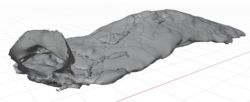
Here's an example. We start from a 3D model of cave, in this case from the small Grottberget cave in Siuntio, Finland:
With the help of the cave-outliner tool, we can read this model and convert it to a plan view and some cross-section views. We use the following command:
cave-outliner --label --dimensions --borderline \
              --multiplier 4 --step 0.05 --holethreshold 10 --formanalysis 1 \
              --crosssectionwidth 3 --crosssections x 3 cross%.svg \
              test/cave1.stl planview.svg
The first line of options specifies that we'd like to show cave dimensions, label cross sections, and show the borderline of the cave in the views. The second line of options is some parameters that adjust the accuracy and size of the resulting images, and allows some small holes (recording imperfections) in the model to be "filled in" to avoid seeing them in the plan view. The form analysis option asks the tool to analyze all cave shapes, e.g., for entrances or stalactices. If your model processing takes a long time, try first without this option, as it will significantly increase the processing load.
The third line of options requests three cross sections to be drawn. Finally, the fourth line has the input file (in STL format) and output image file (in SVG format).
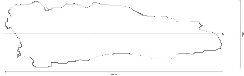
This is the resulting plan view:
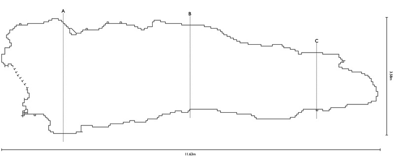
Notice the entrance on the left end of the cave. And this is one of the three resulting cross-section views:
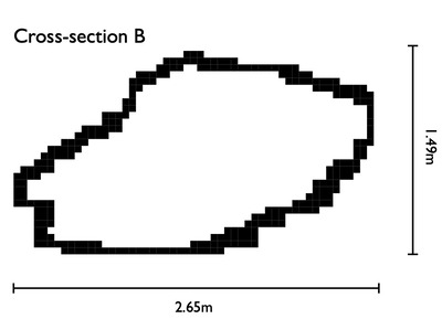
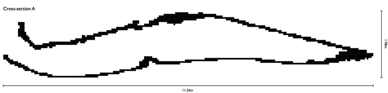
We might also take a cross-section along the length axis, like this:
cave-outliner --label --dimensions --borderline \
              --multiplier 4 --step 0.05 --holethreshold 10 --formanalysis 1 \
	  --crosssectionwidth 3 --crosssections y 1 long-cross.svg \
              test/cave1.stl long-planview.svg
Here the parameters on the third line are slightly different, as we are drawing a cross section at a point in y axis. Here's the resulting cross section:
The plan view also changed, as it shows where the cross sections are:
Here's a more detailed description of the command and its options:
cave-outliner [options] inputfile outputfile
Options:
--auto                    Use default options for best cave map generation.
--bounding x x y y z z    Set the bounding box area. Default is the the model's bounding box.
--step i                  Set the granularity increment. Default is 1.
--z                       Generate output as viewed from the z direction, i.e.,
                          showing x/y picture.
--x                       Generate output as viewed from the x direction, i.e.,
                          showing z/y picture.
--y                       Generate output as viewed from the y direction, i.e.,
                          showing x/z picture.
--pixel                   Use the pixel output drawing algorithm (default, fills cave
                          with pixels).
--pixelform               Same as --pixel, but color pixels based form analysis.
--triangle                Use the triangle output drawing algorithm (draws model faces
                          in plan view).
--depthmap                Same as --pixel, but color pixels based on their height.
--depthdiffmap            Same as --pixel, but color pixels based on their height
                          difference from neighbouring pixels.
--borderpixel             Use the border-only drawing algorithm, draws only the cave
                          walls, with pixels.
--borderline              Use the border-only drawing algorithm, draws only the cave
                          walls, with lines.
--borderactual            Use the border-only drawing algorithm, draws the cave walls using
                          model triangle sides.
--crosssection d p [file] Produce also a cross section at a given direction (d = x or y),
                          position p, output to file 'file'.
--crosssections d n [pat] Produce n cross sections at different direction (d = x or y)
                          positions, output to files (percent sign denotes the cross
                          section number in the file name pattern).
--crossectionwidth n      Width of the analysis for a cross section, by default 1.0, i.e.,
                          one step.
--formanalysis f          Analyze cave forms, e.g., entrances, stones, stalactites, etc.
                          Factor f specifies how much the analysis compresses pixels,
                          value of 1 implies no compression.
--no-formanalysis         Turn off form analysis.
--composite               Create a composite cave map file from the plan view and all
                          cross sections.
--name name               The name of the cave.
--surveyer name           Who performed the 3D survey? Default is the user's name who is
                          running this software.
--surveytool name         What tool was used for 3D scan? Default is iPhone 12 Pro.
--surveydate date         When was the survey taken? Default is the creation date of the
                          input file.
--location place          The location of the cave, e.g., city or country.
--coordinates coords      Coordinates of the cave.
--length text             Text to use as the length of the cave in the map.
--floordepthmap file      Output cave tunnel floor depth map to given file.
--roofdepthmap file       Output cave tunnel roof depth map to given file.
--floorstyle s            Specify floor and roof depthmap style, either depth
                          or diff.
--tunnelspine             Mark cave tunnel centerpoints.
--label                   Label cross sections
--dimensions              Show dimensions of each cave plan view and cross section.
--linewidth n             Set the width of the lines in output picture. The value can be a
                          decimal number.
--multiplier n            Multiply image size by n (default 1).
--smooth                  Set the line drawings use smooth curves.
--jagged                  Set the line drawings use hard lines (default).
--svgyreverse             Reverse Y axis in the SVG (to maintain same Y coordinate
                          direction as in the model).
--maxlinemerge            How many line segments may be combined in one SVG line?
--holethreshold n         Ignore holes in the model if they are n or less pixels.
--lineholethreshold n     Ignore holes in cross-section  lines if they are n or less pixels.
--dustthreshold n         Ignore small amount of material if not connected and less
                          than or equal to n pixels.
--tiling n                Optimize search process with n x n tiles. Default is 30,
                          and --tiling 1 implies no optimization.
--parallel n              How many parallel threads can be run.
--quiet                   Turn on informative messages (default is they are on).
--debug                   Turn on debugging messages (level 0, least).
--deepdebug               Turn on debugging messages (level 1).
--deepdeepdebug           Turn on debugging messages (level 2, most).
--version                 Output version information.
--help                    Print this message.
Please read the installation guide.
Algorithms for drawing plan and other views based on a 3D are discussed in the paper.
The structure of the software is discussed in the design document.