A NES Emulator for the Raspberry PI Pico with SD card and menu support. You can use it with:
- Pimoroni Pico DV Demo Base hdmi add-on board.
- Adafruit DVI Breakout For HDMI Source Devices and Adafruit Micro-SD breakout board+ together with a breadboard.
- MURMULATOR Platform Base
- A custom printed circuit board designed by @johnedgarpark. A NES or SNES controller port can be soldered on this PCB.
The emulator used is Infones by Jay Kumogata which was ported to the Raspberry PI Pico by Shuichi Takano with changes done by me to accomodate the SD card menu.
In stead of flashing a NES rom to the Pico using picotool, you create a FAT32 formatted SD card and copy your NES roms on to it. It is possible to organise your roms into different folders. Then insert the SD Card into the card slot of the Pimoroni Pico DV Demo base. Needless to say you must own all the roms you put on the card.
A menu is added to the emulator, which reads the roms from the SD card and shows them on screen for the user to select, flash and play.
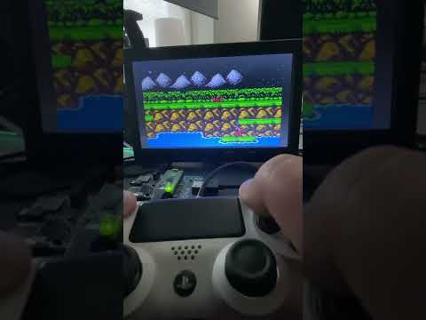
Click on image below to see a demo video.
There is also a version available for the Pimoroni PicoSystem handheld.

Repeatedly flashing your Pico will eventually wear out the flash memory.
The emulator overclocks the Pico in order to get the emulator working fast enough. Overclocking can reduce the Pico's lifespan.
Use this software at your own risk! I will not be responsible in any way for any damage to your Pico and/or connected peripherals caused by using this software.
I also do not take responsability in any way when damage is caused to the Pico or display due to incorrect wiring or voltages.
The emulator supports these controllers:
- Sony Dual Shock 4
- Sony Dual Sense
- BUFFALO BGC-FC801 (not tested)
- An original NES controller. See below for wiring.
- Raspberry Pi Pico with soldered male headers.
- Pimoroni Pico DV Demo Base.
- Micro usb to usb OTG Cable
- Dual Shock 4 or Dual Sense Controller.
- HDMI Cable.
- Micro usb power adapter.
- Micro usb to usb cable when using the Duak Shock 4 controller
- usb C to usb cable when using the Sony Dual Sense controller.
- FAT 32 formatted Micro SD card with roms you legally own. Roms must have the .nes extension. You can organise your roms into different folders.
- Download piconesPlusPimoroniDV.uf2 from the releases page.
- Push and hold the BOOTSEL button on the Pico, then connect to your computer using a micro usb cable. Release BOOTSEL once the drive RPI-RP2 appears on your computer.
- Drag and drop the UF2 file on to the RPI-RP2 drive. The Raspberry Pi Pico will reboot and will now run the emulator.
- Disconnect the Pico from your computer.
- Attach the Pico to the DV Demo Base.
- Connect the HDMI cable to the Demo base and your monitor.
- Connect the usb OTG cable to the Pico's usb port.
- Connect the controller to the other end of the usb OTG.
- Insert the SD card into the SD card slot.
- Connect the usb power adapter to the usb port of the Demo base.
- Power on the monitor and the Pico

- Raspberry Pi Pico with soldered male headers.
- Adafruit DVI Breakout For HDMI Source Devices
- Adafruit Micro-SD breakout board+
- Micro usb to OTG Y-Cable
- Breadboard
- Dual Shock 4 or Dual Sense Controller.
- HDMI Cable.
- Micro usb power adapter.
- Usb C to usb cable when using the Sony Dual Sense controller.
- Micro usb to usb cable when using a Dual Shock 4.
- FAT 32 formatted Micro SD card with roms you legally own. Roms must have the .nes extension. You can organise your roms into different folders.
- Download piconesPlusAdaFruitDVISD.uf2 from the releases page.
- Push and hold the BOOTSEL button on the Pico, then connect to your computer using a micro usb cable. Release BOOTSEL once the drive RPI-RP2 appears on your computer.
- Drag and drop the UF2 file on to the RPI-RP2 drive. The Raspberry Pi Pico will reboot and will now run the emulator.
Use the breadboard to connect all together:
- Wire Pico Pin 38 to the breadboard ground column (-)
- Wire the breadboard left ground column (-) with the breadboard right ground column (-)
| Breakout | GPIO | Pin number |
|---|---|---|
| CS | GP5 | 7 |
| CLK (SCK) | GP2 | 4 |
| DI (MOSI) | GP3 | 5 |
| DO (MISO) | GP4 | 6 |
| 3V | 36 | |
| GND | Ground on breadboard (-) |
| Breakout | GPIO | Pin number |
|---|---|---|
| D0+ | GP12 | 16 |
| D0- | GP13 | 17 |
| CK+ | GP14 | 19 |
| CK- | GP15 | 20 |
| D2+ | GP16 | 21 |
| D2- | GP17 | 22 |
| D1+ | GP18 | 24 |
| D1- | GP19 | 25 |
| 5 (*) | VBUS | 40 (5volt) |
| GND (3x) | Ground on breadboard (-) |
(*) This is the via on the side of the board marked 5. (next to via D and C).

- Disconnect the Pico from your computer.
- Attach the Pico to the breadboard.
- Insert the SD card into the SD card slot.
- Connect the HDMI cable to the Adafruit HDMI Breakout board and to your monitor.
- Connect the usb OTG Y-cable to the Pico's usb port.
- Connect the controller to the full size female usb port of the OTG Y-Cable
- Connect the Micro usb power adapter to the female Micro usb connecter of the OTG Y-Cable.
- Power on the monitor and the Pico
See image below. Note. The Shotky Diode (VSYS - Pin 39 to breadboard + column) and the wire on breadboard left (+) to right (+) are not necessary, but recommended when powering the Pico from a Raspberry Pi. See Chapter 4.6 - Powering the Board of the Raspberry Pi Pico Getting Started guide


Create your own little Pico Based NES console and play with an orginal (S)NES controller. Soldering skills are required. The PCB design files can be found in the assets/pcb folder. Several Companies can make these PCBs for you.
I personally recommend PCBWay. The boards i ordered from them are of excellent quality.

Simply upload the design files packed as a zip archive when ordering. A zip file containing the design files can be found on the releases page.
Other materials needed:
- Raspberry PI Pico with no headers.
- on/off switch, like this
- Adafruit DVI Breakout Board - For HDMI Source Devices
- Adafruit Micro SD SPI or SDIO Card Breakout Board - 3V ONLY!
- Optional a NES Controller port if you want to play using an original NES controller.
- Optional a SNES controller port. if you want to play using an original SNES controller.
- Optional Micro usb to OTG Y-Cable for connecting a Dualshock/Dualsense controller.
- Micro USB power supply.
Flash the Pico with piconesPlusAdaFruitDVISD.uf2 from the releases page.

Gamepad buttons:
- UP/DOWN: Next/previous item in the menu.
- LEFT/RIGHT: next/previous page.
- A (Circle): Open folder/flash and start game.
- B (X): Back to parent folder.
- START: Starts game currently loaded in flash.
Gamepad buttons:
- SELECT + START: Resets back to the SD Card menu. Game saves are saved to the SD card.
- SELECT + UP/SELECT + DOWN: switches screen modes.
- SELECT + A/B: toggle rapid-fire.
For games which support it, saves will be stored in the /SAVES folder of the SD card. Caution: the save ram will only be saved back to the SD card when quitting the game via (START + SELECT)
The emulator works with the Pico W, but without the onboard blinking led. In order for the led to work on the Pico W, the cyw43 driver needs to be initialised. This causes the emulator to stop with an out of memory panic.
- Make sure the board is directly connected to your display. Do not connect through a HDMI splitter.
- When using the Adafruit HDMI board, make sure VBUS (Pin 40) is connected to the 5 volt via on the board. (Marked 5 on the side) Some displays need 5V in order to work.
- Pimoroni Pico DV: Audio through the audio out jack is not supported, audio only works over hdmi.
- Due to the Pico's memory limitations, not all games will work. Games not working will show a "Mapper n is unsupported." (n is a number). For example starting Castlevania III will show the "Mapper 5 is unsupported." message.
- tar file support is removed.
- Pico W: The onboard led does not blink every 60 frames.
IMPORTANT The emulator does not run when built with the latest version (1.5.0) of the Pico SDK. Use 1.4.0 in stead. See issue #7
The emulator and menu system take almost the whole ram. Therefore, the Release build is too big to fit into the Pico's ram, and cannot be used. Also the MinSizeRel (Optimise for smallest binary size) build is not suitable, because it makes the emulator too slow.
Best is to use the included build script buildAll.sh. You can then copy the.uf2 to your Pico via the bootsel option. The script builds two .uf2 files (Pimoroni and Adafruit) and puts them in the assets folder.
When using Visual Studio code, choose the RelWithDebInfo or the Debug build variant.
InfoNes is programmed by Jay Kumogata and ported to the Raspberry PI Pico by Shuichi Takano.
I contributed by adding SD card and menu support. For this reasons I made code changes to the emulator for accommodating the menu and SD card.
PCB design by @johnedgarpark.
NES gamepad support contributed by PaintYourDragon & Adafruit. If using Pimoroni Pico DV Demo Base: NES controller clock, data and latch go to GPIO pins 14, 15 and 16, respectively. If Adafruit DVI Breakout build, it's GPIO pins 6, 7, 8 instead. Gamepad should be powered from 3.3V when connected to Pico GPIO, not 5V as usual...seems to work OK regardless. Controller ports which can be wired up to the Pimoroni DV or breadboard can be found here
