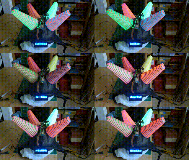
Mark2 Tin-Foil hat
A version of the LdgDisplay for my friend Peter Christy.
- Independently controllable LED sign-board and cones wrapped with EL wires
- LED Sign-Board
- 21x7 array of blue LEDs
- Multiple built-in fonts, including symbols
- Continually scrolls (arbitrarily long) strings
- Individual strings can be composed of characters from different fonts
- EL Wire Cones
- four cones, each with two independent (different colored) EL wires
- selectable pattern and speed
- LED Sign-Board
- Persistent storage of configuration parameters
- i.e., WiFi settings, LED display string, and EL cone pattern and speed
- Built-in web-server-based GUI
- OTA updateable firmware
- Powered by (micro-USB) rechargable (LiPo) battery
- Standalone web-server-based status/control interface
The PrcDisplay device is controlled by a web interface through it's web server.
To connect to the device's web server you point a web browser at the IP address of the device. On power-up the device attempts to connect to a WiFi access point (AP) using the SSID and password stored in it's local (non-volatile) file system. Should the device not be able to successfully connect to the given AP, it becomes an AP itself and allows other devices to connect to it (via a well-known SSID with no password).
TBD: describe how to connect a smartphone to the device, also describe how to get the device's IP address
N.B. This is insecure in that it stores and exchanges the WiFi password (effectively) in the clear -- you've been warned...
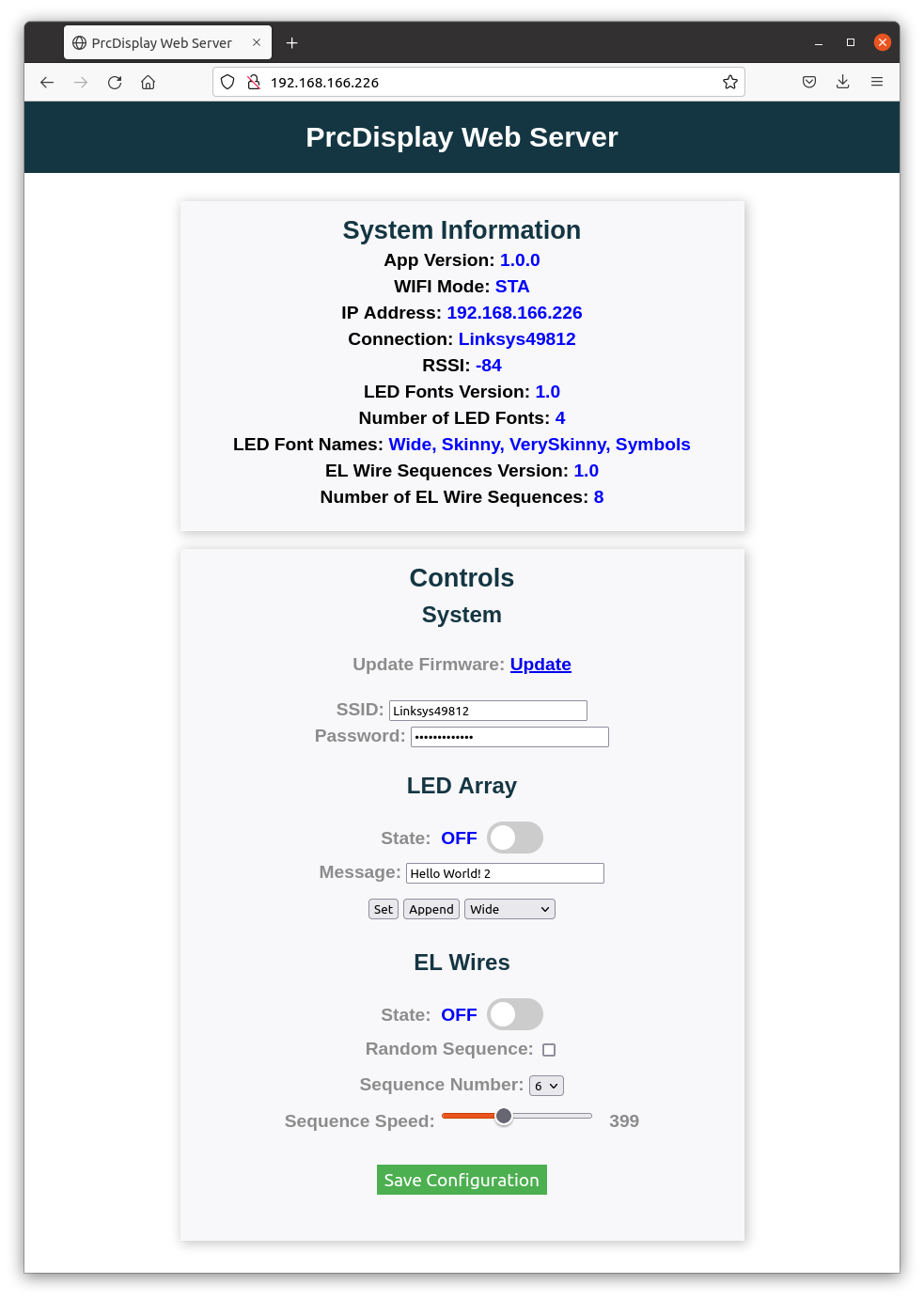
At the top level, the web interface has two sections ("cards") -- one that provides (static between reboots) system information, and another that provides the ability to change the operating parameters of the device, update its firmware load, and save the configuration to its (non-volatile) local file system.
The System Information card indicates the version of the application, details concerning the current WiFi connection, the currently installed LED display fonts, and the EL wire sequences.
The green button marked "Save Configuration" at the bottom of the "Controls" card causes the current configuration to be saved to the device's local file system. The information saved includes all of the settings shown on the card. The web interface uses web-sockets and should allow multiple concurrent users, but no effort has been made to ensure consistent views/updates are done -- the initial assumption is that there is a single user controlling the device at any time.
The message to be displayed by the LED array is composed by entering text into the "Message" field, selecting the desired font (from the pull-down box below the message), and either appending the given text to the current message (via the "Append" button), or making the current text be the entire message (via the "Set" button). The append mechanism is used to create messages that contain characters with different fonts.
The LED sign-board can be turned on and off by way of the toggle switch following the indication of its current (on/off) state.
The manner in which the EL wires are driven is defined by a repeating sequence of wire on/off patterns. Either a random pattern, or one of the pre-defined sequences can be chosen via the GUI, and the speed at which successive patterns within a sequence are displayed can also be selected.
The WiFi access point to which the device will attempt to connect at power up can be given by an SSID and associated password in the "System" section of the Controls card. These values are written to the device's file system by pressing the "Save Configuration" button; nothing happens until this is done.
Clicking "Update" next to the "Update Firmware" line will bring up a new web page that allows a pre-compiled binary to be loaded to become the device's new firmware load.
TBD: Add description of how to generate binary files
Alternatively, a (Linux or Windows) machine can be connected to the ESP8266 via its micro-USB port and code can be loaded via the Arduino IDE.
The firmware for the PrcDisplay device is written in C++ using the Arduino stack for the ESP8266. Information on how to install this stack is given here FIXME
The code consists of a main application (PrcDisplay.ino) and a pair of custom libraries
In addition to several stock Arduino libraries, this application relies on two custom libraries -- one for controlling the AFD driver board and another for driving the LED array.
This library drives the PrcDisplay's EL wires with different sequences of patterns, at different speeds. The sequences of patterns that can be selected are compiled into the PrcDisplay.ino application and are generated by the tools/seqgen.c code.
This library is used to generate scrolling messages (potentially, using multiple fonts) on a small LED arrays (i.e., ones with less than or equal to 32 columns). It is designed to drive the LED array from an in-core bitmap, using a set of 74HC595 shift registers to enable the LEDs in the array. This uses the 'ShiftRegister74HC595' library to set the LEDs' pin values to their desired states.
The 'tools/' directory includes a few tools that help in the creation and management of the PrcDisplay.
This tool polls for devices joining and leaving a given range of local network address. This can be used to determine the IP address of the PrcDisplay when it attaches to a WiFi network.
This directory includes a program (named 'fontgen') that takes a collection of bitmap font descriptions (in the form of header files that include initialized 'Font' data structure). The program generates a C++ header file that can be included by the PrcDisplay.ino application to define the fonts usable by the LED array.
The program named 'seqgen' takes definitions of sequences of EL wire patterns (in 'seqdefs.h') and generates a C++ header file that can be included by the PrcDisplay.ino application to define the set of EL wire pattern sequences that can be selected for the EL wires.
The hardware consists of an ESP8266 controller, an AFD EL driver board, eight EL wires, an LED array sign-board, a high-voltage power supply, a DC step-up converter, a LiPo charger/regulator/step-up converter board, and a LiPo battery.
TBD
- Main controller, programmed in C++ using Arduino libraries
TBD
- AFD Driver Board: driver for EL wires Alien Font Display driver board
- Two 9' EL wires on each of four cones
- I2C-controlled via PCF8574A eight-bit port expander
- foam cones
- notched 3mm wide 3mm deep
- made wire support frames from laser-cut acrylic
TODO add CAD files for supports
- Blue LED array with 21 columns and 7 rows (modified LED badge)
- Driven by four 74HC595 8-bit shift registers
- columns are active low and rows are active high
- layout: assume pixel at location (0,0) is in the upper right corner
- srValues[3]: first eight columns
-
- active low
-
- srValues[2]: middle seven columns
-
- active low
-
- srValues[1]: top three rows and last five columns
-
- active high
-
- active low
-
- srValues[0]: bottom four rows
-
- active high
-
- srValues[3]: first eight columns
- layout: [nc3:0, rows[6:3]], [rows[2:0], cols[20:16]], [cols[15:8]], [cols7:0]
As the PrcDisplay is designed to be a wearable standalone unit, it is powered by a LiPo battery
Considerable power in the range of 80-130VAC is required to drive the EL wires. Each EL wire consumes up to 1.5W per meter of length. This device uses eight 2.7 meter wires, which translates to about 32W of power.
While the EL wires can be lit up with AC in the range of 450-3KHz, higher frequencies reduce the wires' lifetimes. Furthermore, while PSUs can be found that operation with 3.3-5V inputs, to drive the kind of EL wire loads in this project, the commercially-available HV-PSUs that I've been able to locate use 12V inputs.
The PrcDisplay device uses the Elumiglow EO125 HV-PSU that takes 12VDC as input and generates a (nominal) 105VAC output at 1,760Hz. Note that this HV-PSU does emit a high-pitched whine. Other HV-PSUs are available that claim to be "silent", but I wasn't able to find one that provided similar drive specs. Other suppliers of such HV-PSUs include CoolLight.
TBD provide reference to the part
To provide the 12VDC required by the HV-PSU, a 5V to 12V step-up converter module was used.
TBD provide reference to the part
????
3.7V, 2000mAh LiPo battery
TBD provide reference to the controller and battery
????
TBD provide reference to the part and goggles
- make Kicad schematics for everything and add them to this repo
- DRY up the config code in PrcDisplay.ino
- add script to find IP address of device
- V2 features
- battery level
- Audio input
- dynamic displays based on audio (frequency-/amplitude-based displays)
- STT -- display what it hears
- my network assigns the device a symbolic name of the form "ESP-xxxxxx.lan" (where 'xxxxxx' is the last six hex digits of the MAC address.

