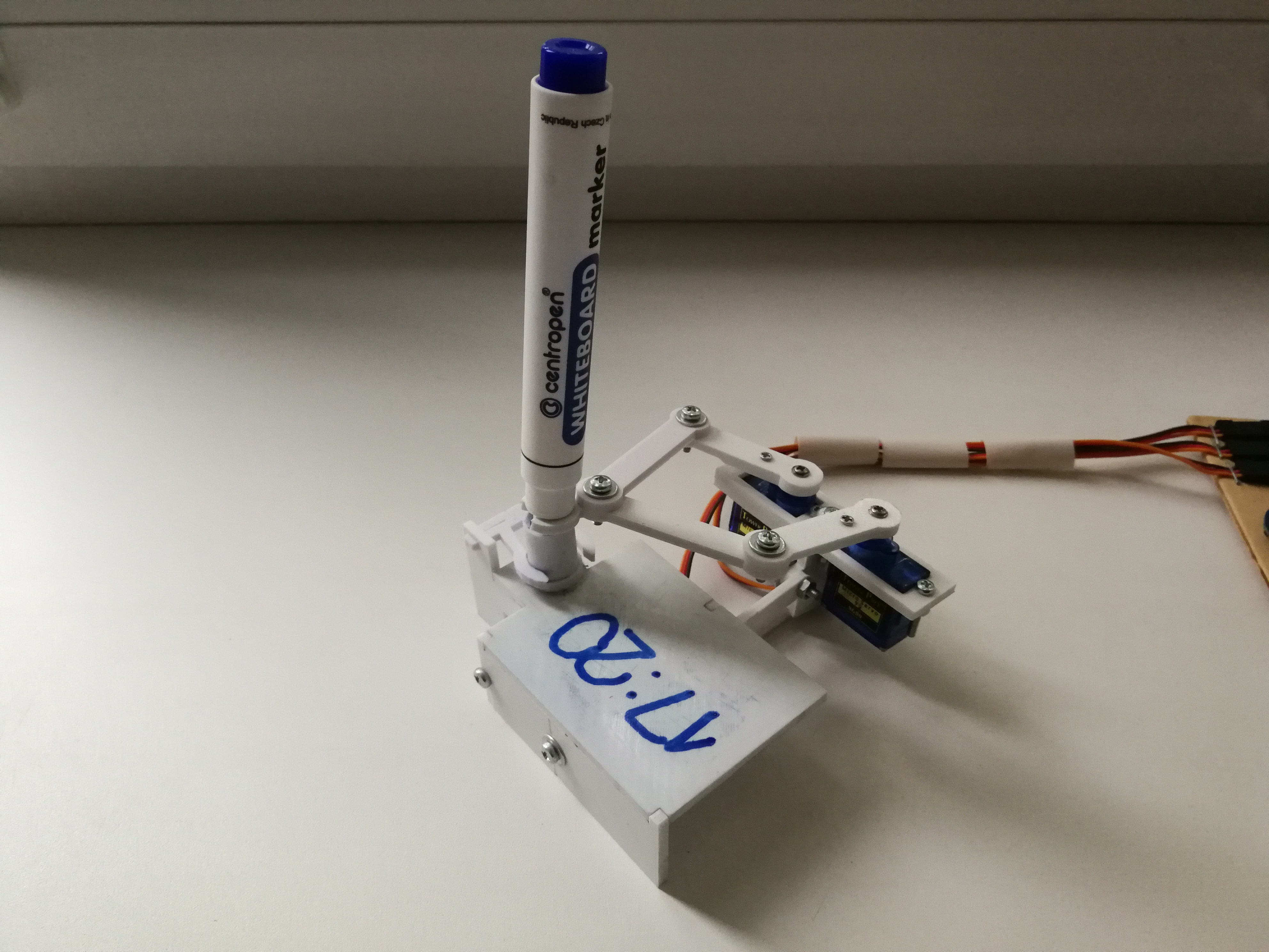
A robotic clock that writes current time with a marker.
The way it functions is simple: the robot draws the time on every new minute. At the beginning of a minute previously drawn time becomes erased and new one appears on the board again.
- Prerequisites
- Getting Components Ready
- Assembling
- Firmware
- Operating Details
- Customization
- Known Issues
- Acknowledgments
- Arduino IDE;
- KOMPAS-3D v18 in case you want to customize components.
- Arduino UNO (any Rev);
- SG90 servo motors - x3;
- LM2596S step-down voltage regulator;
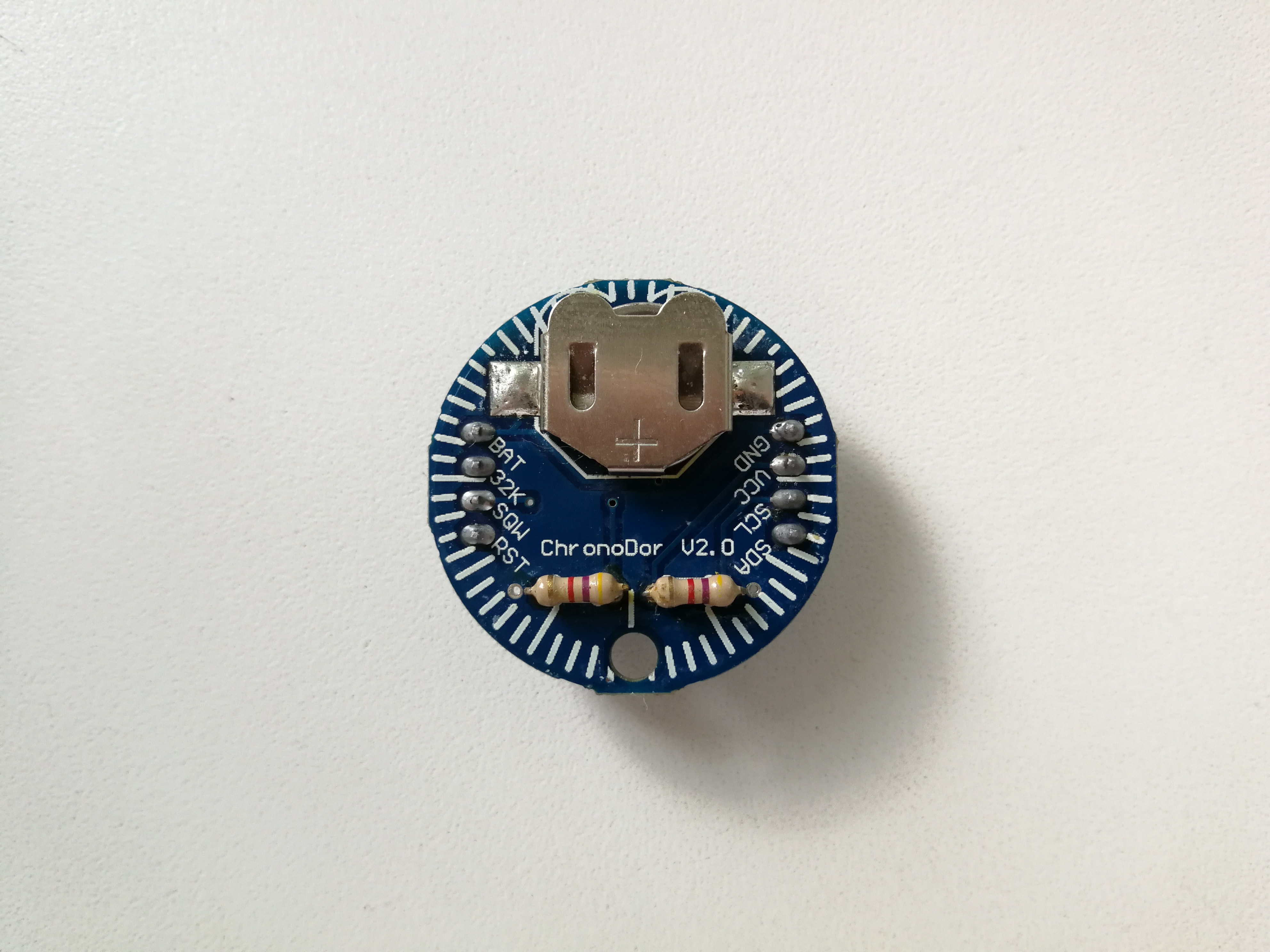
- ChronoDot V2.0 real time clock module;
- 4.7k Ohm resistors - x2 (for ChronoDot module);
- CR2016 battery;
- 5.5 x 2.1mm DC Female to 2 Male power splitter cable;
- 5.5 x 2.1mm power jack socket;
- DC power supply 12V 2A;
- Whiteboard marker (dry-wipe);
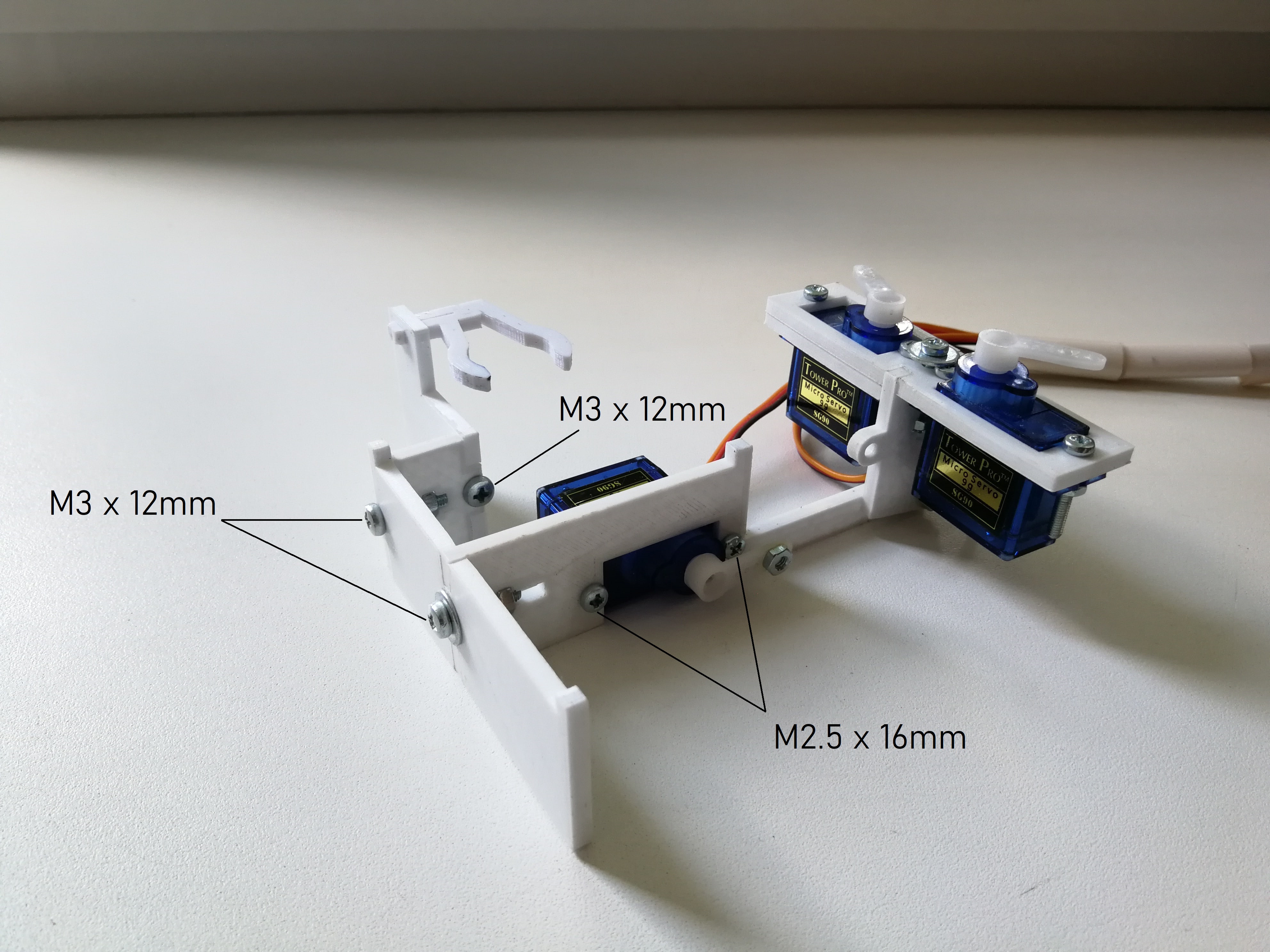
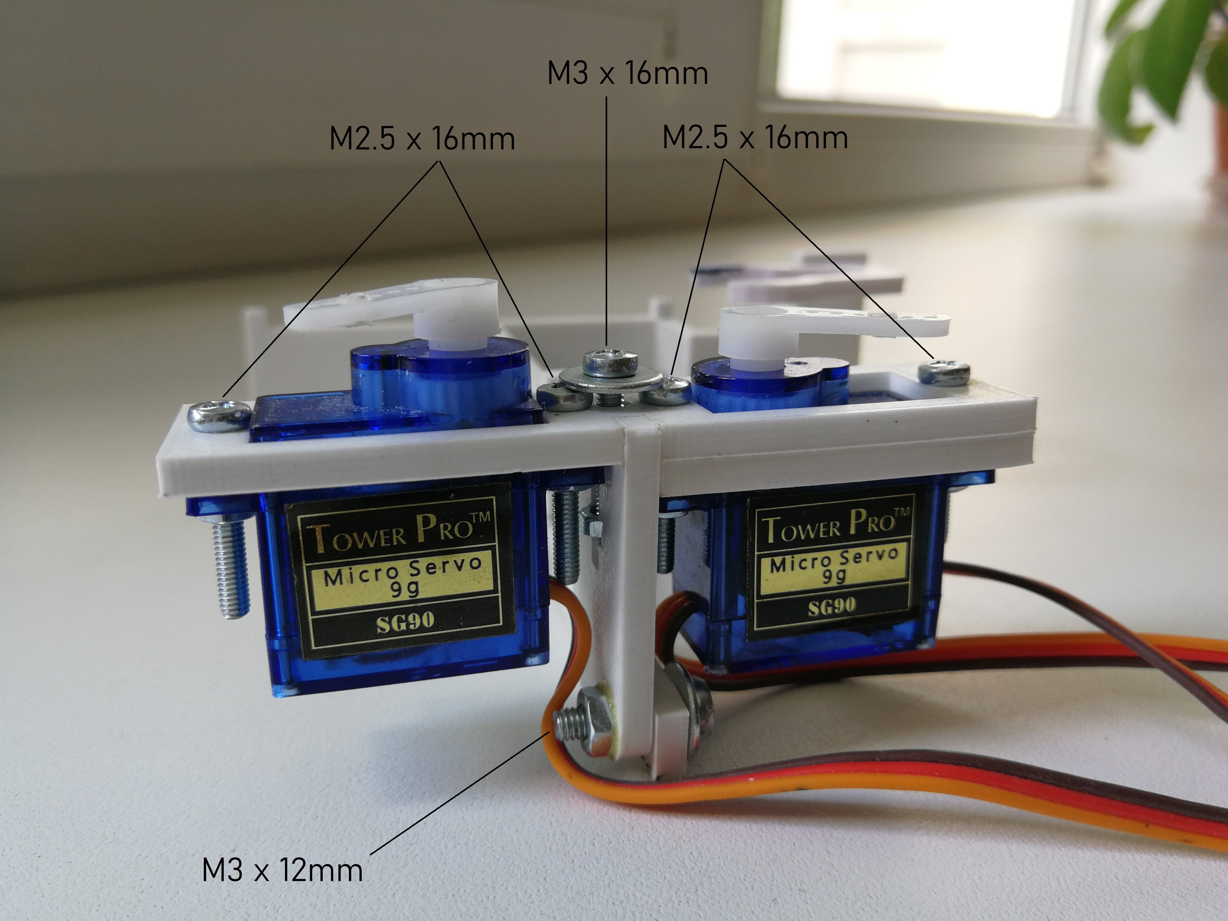
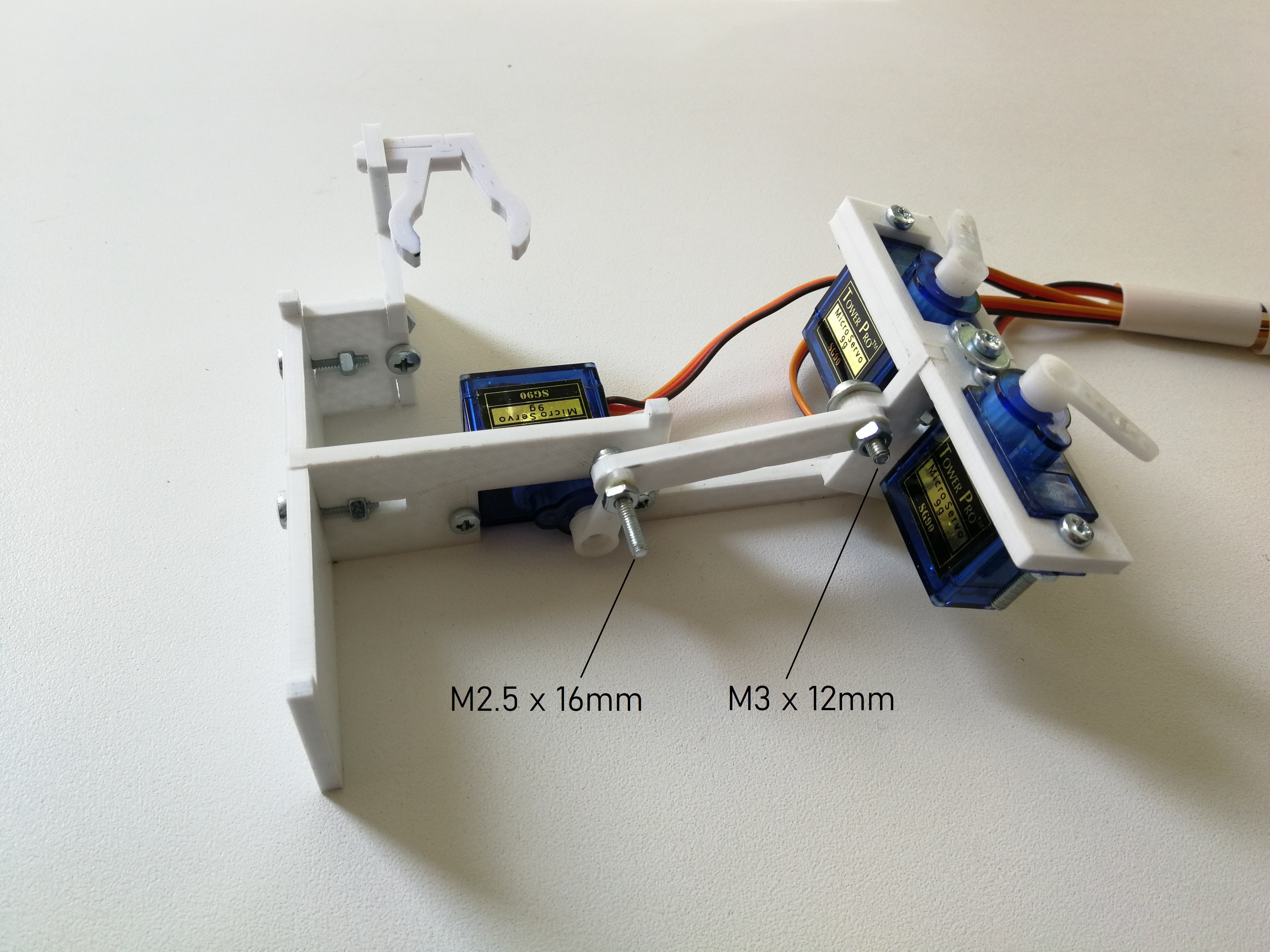
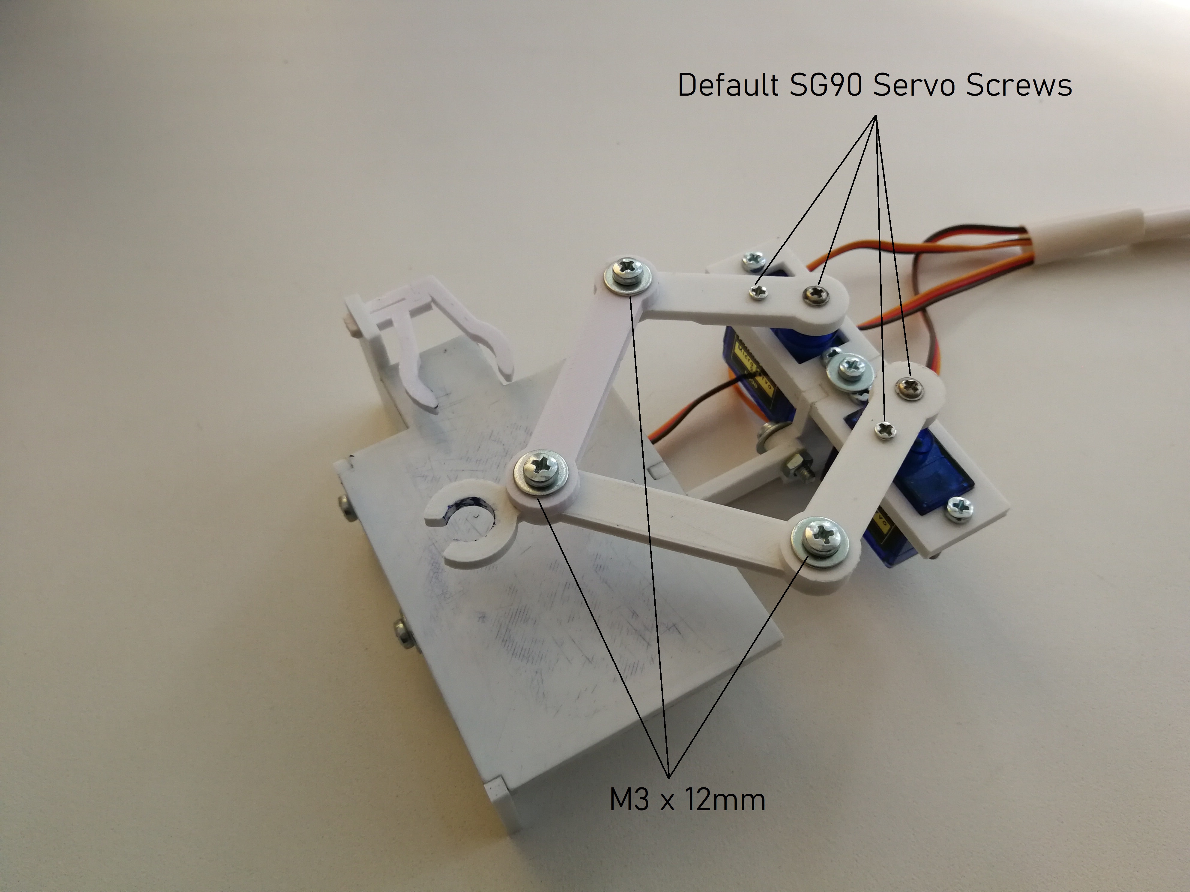
- M3 x 12mm pan head screws - x8;
- M3 x 16mm pan head screws - x1;
- M2.5 x 16mm pan head screws - x7;
- M3 nuts - x9;
- M2.5 nuts - x7;
- M3 washers - x7;
- M2.5 washers - x1;
- SG90 default screws;
- Jumper wires;
- Some glue;
- Some screws and nuts to fix the circuits.
It is designed to print all of the robot components with 3d-printer. But you are free to choose another way to produce them.
You can find 3d-models of components under plotclock_details directory. There are both separate files for each component and all_in_one file that contains all of them. Both are exported to STL format and ready to print.
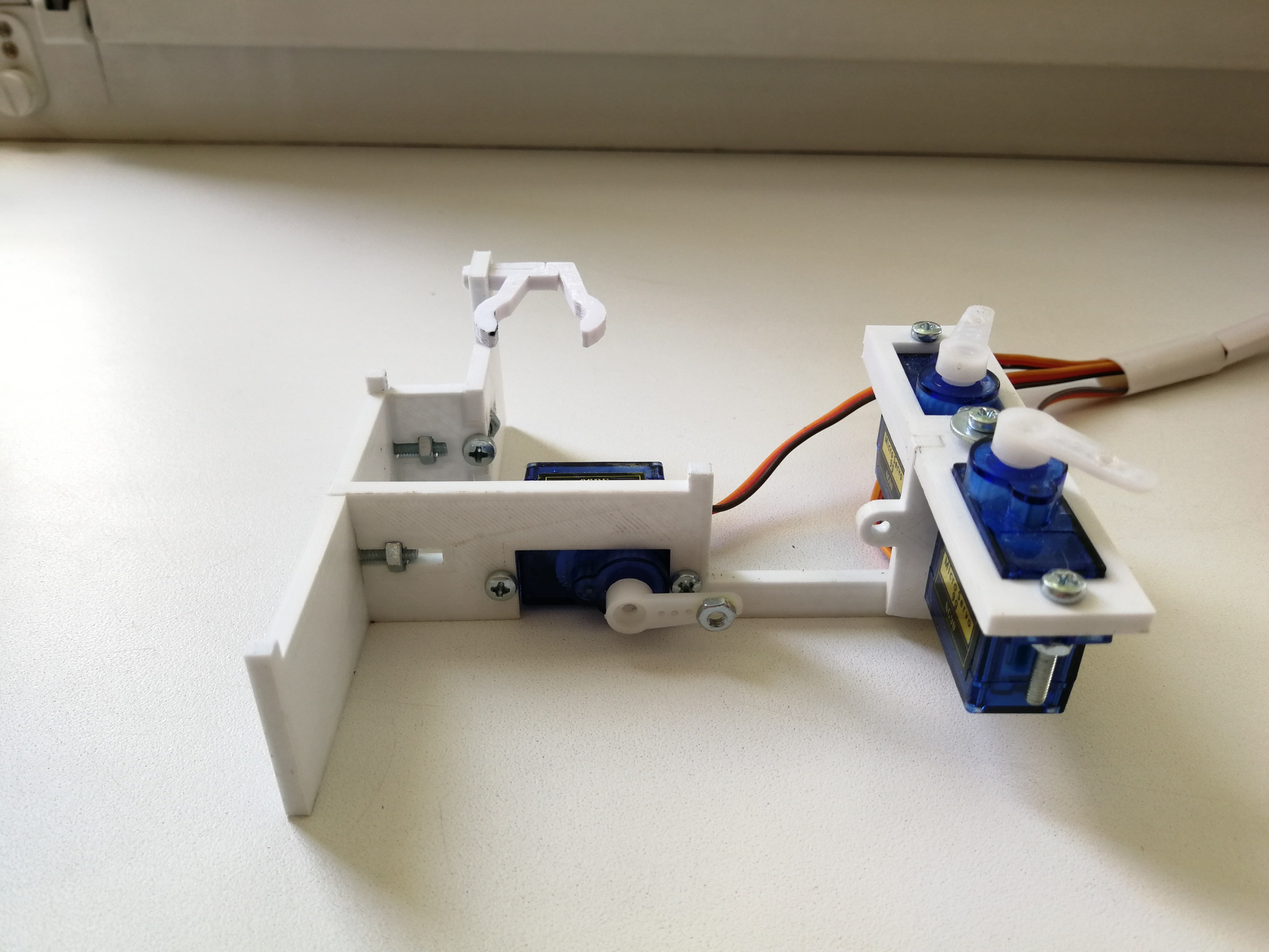
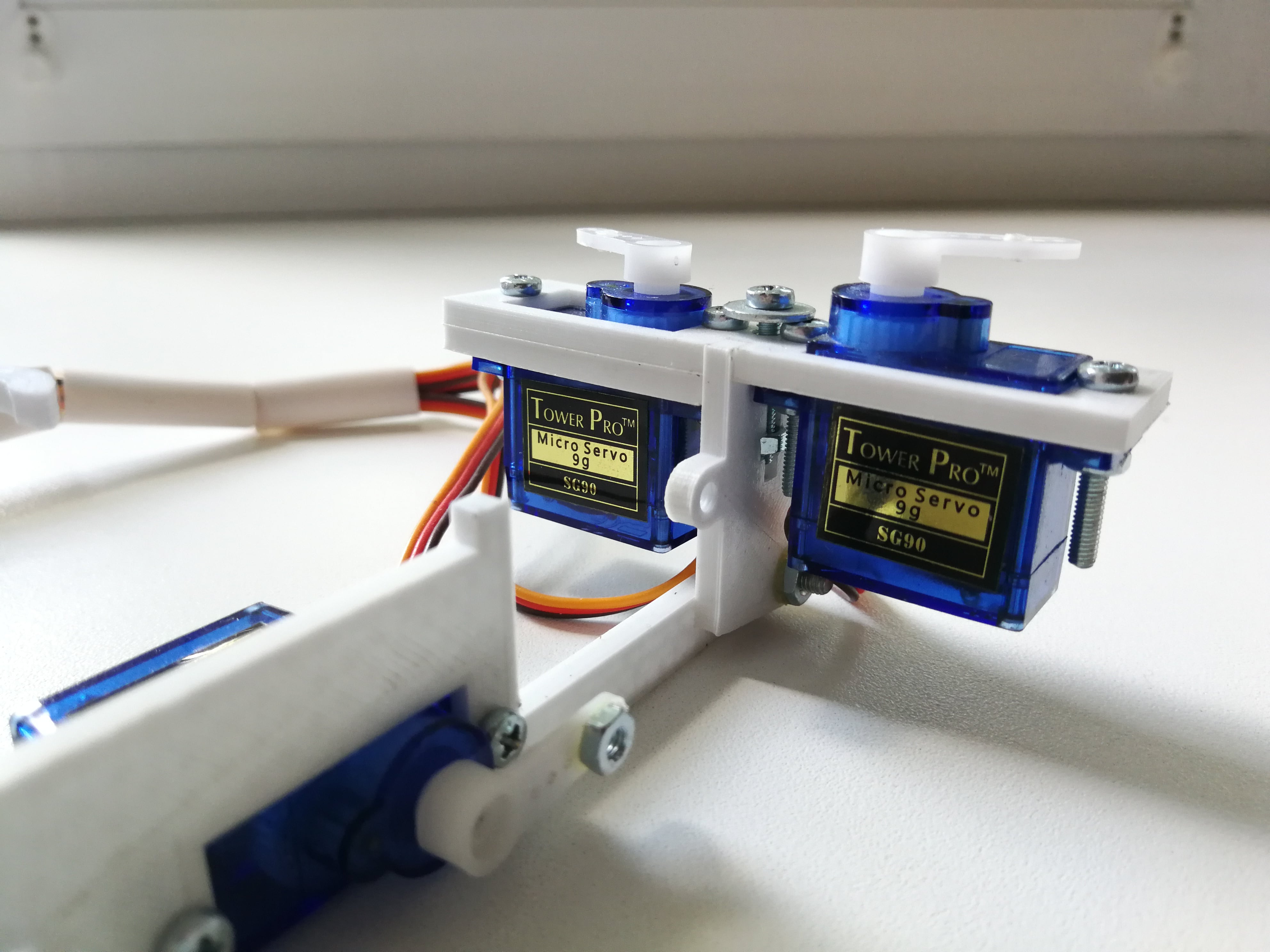
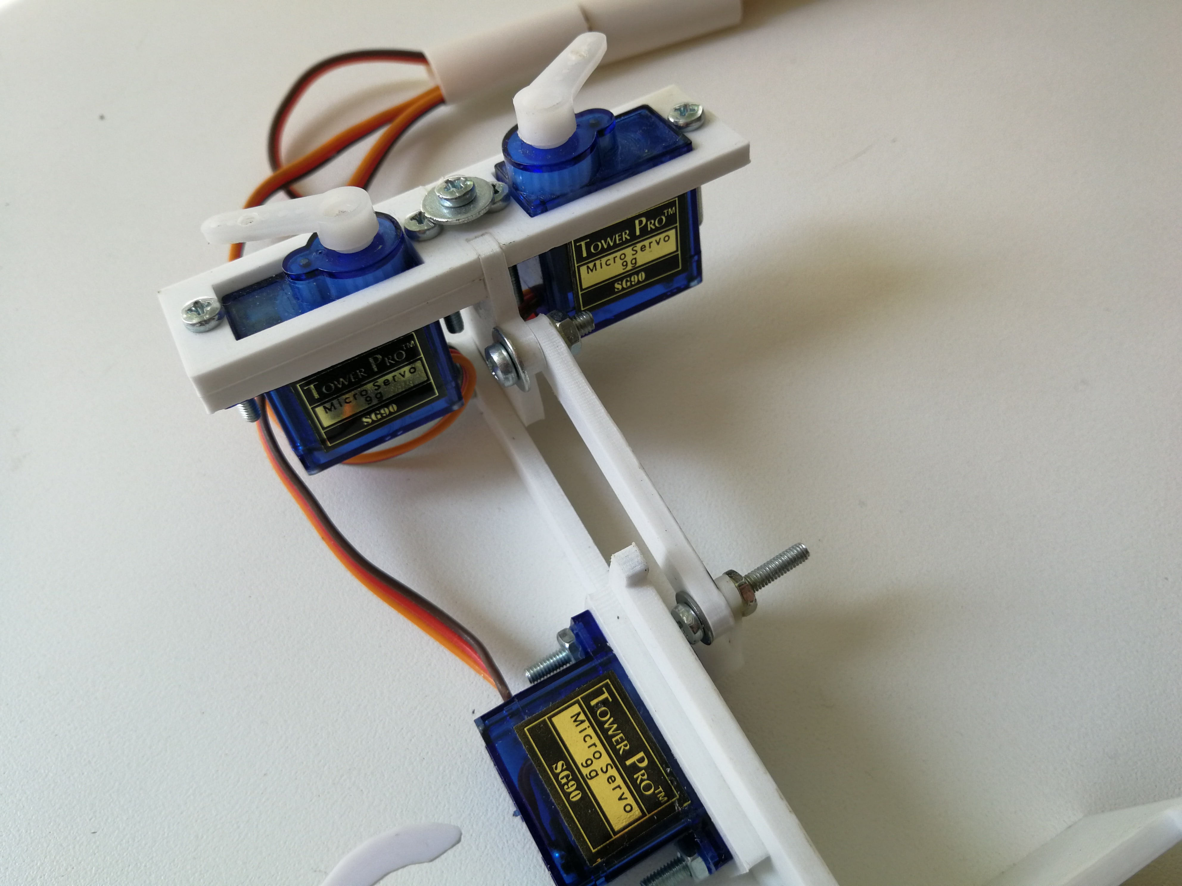
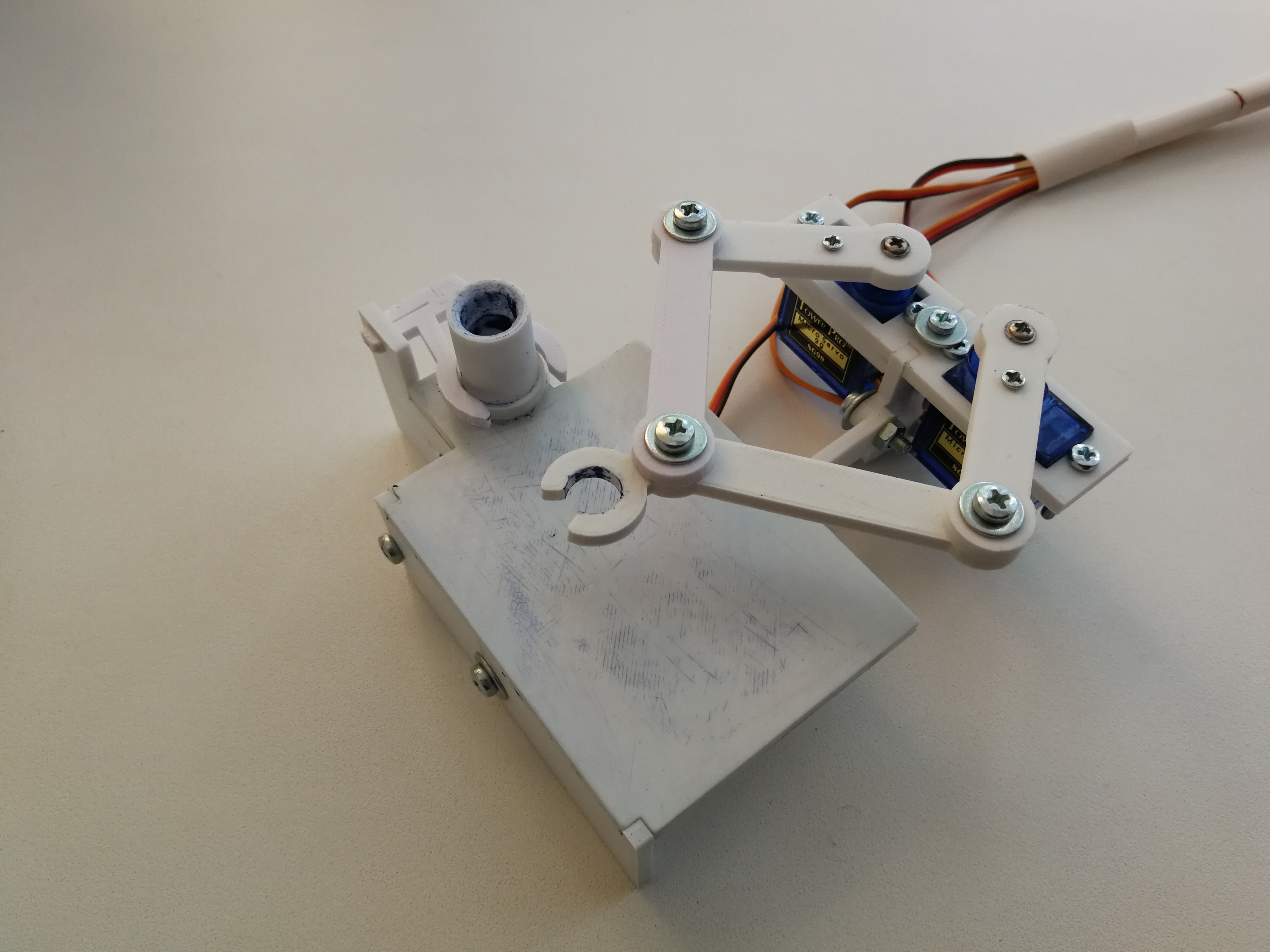
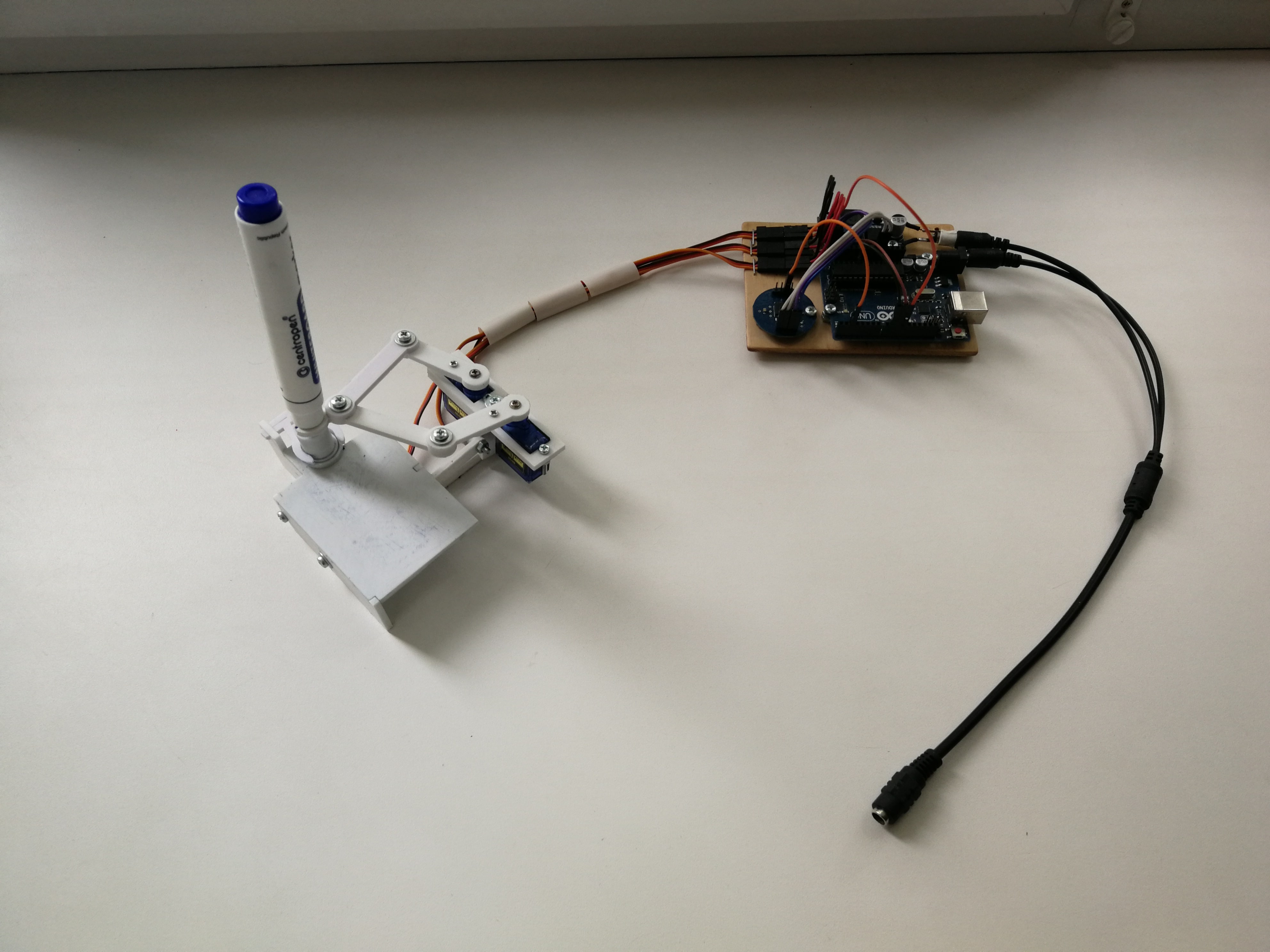
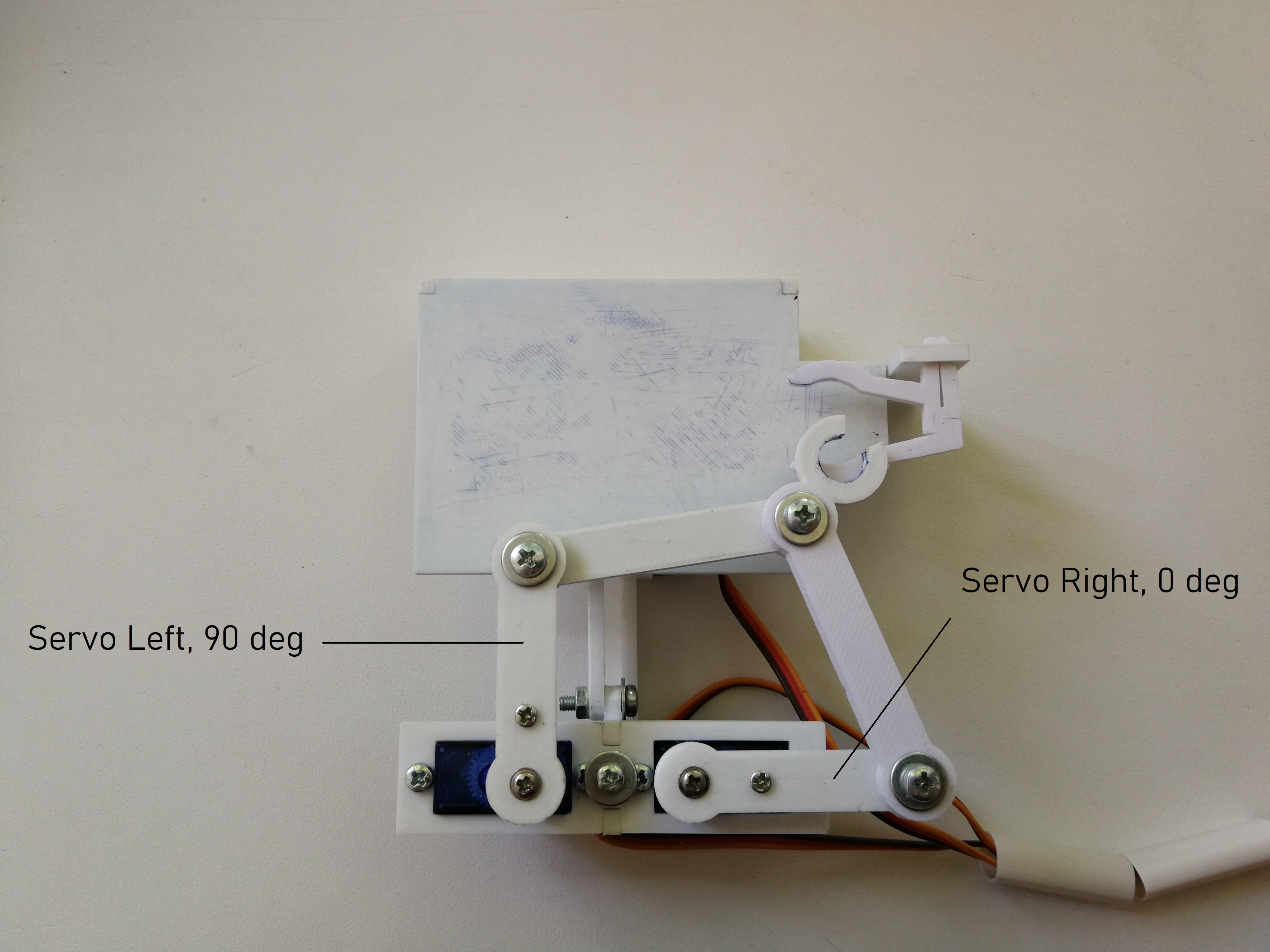
Put components together according to pictures below.
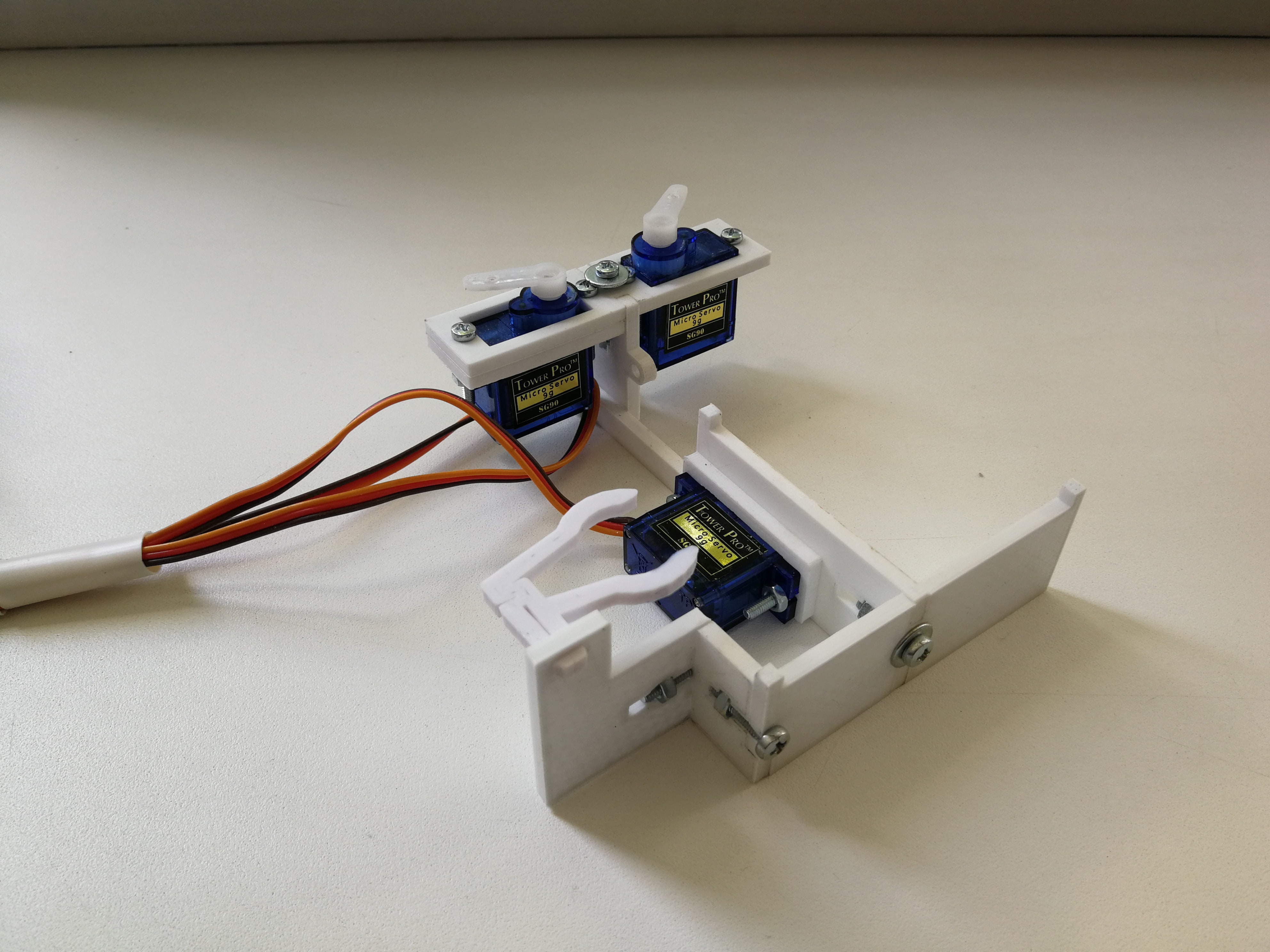
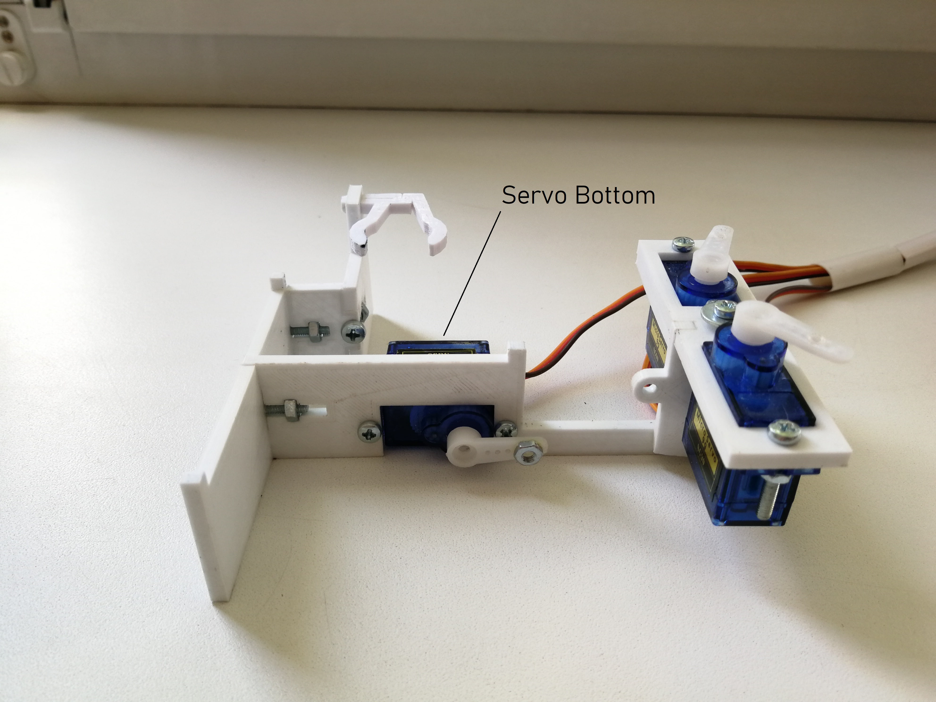
Before joining default servo levers to servos themselves (on the pictures above they have already been joined), set servo shafts in corresponding positions:
- servo bottom: all the way to the end of min angle;
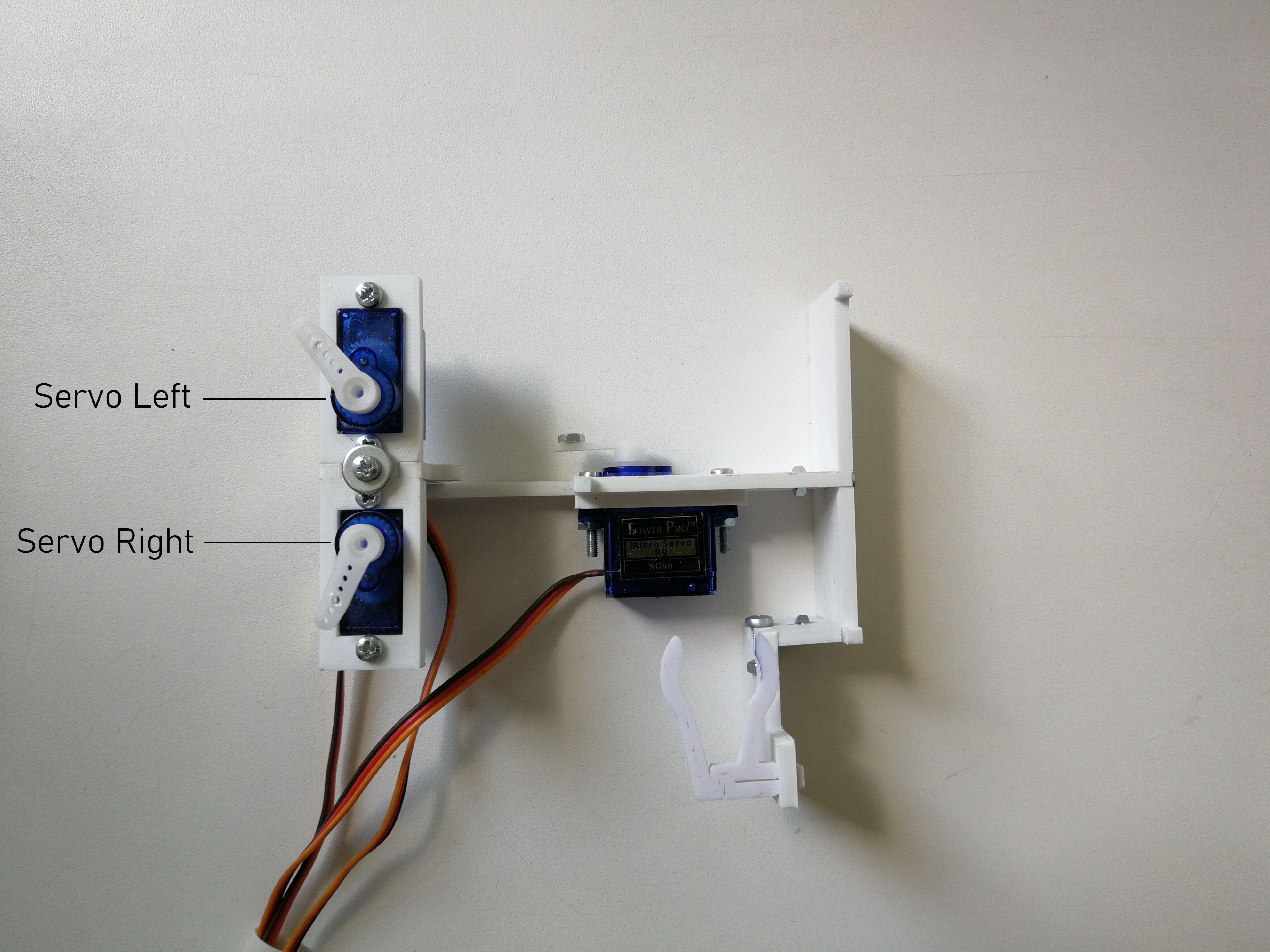
- servo right: all the way to the end of min angle;
- servo left: all the way to the end of max angle.
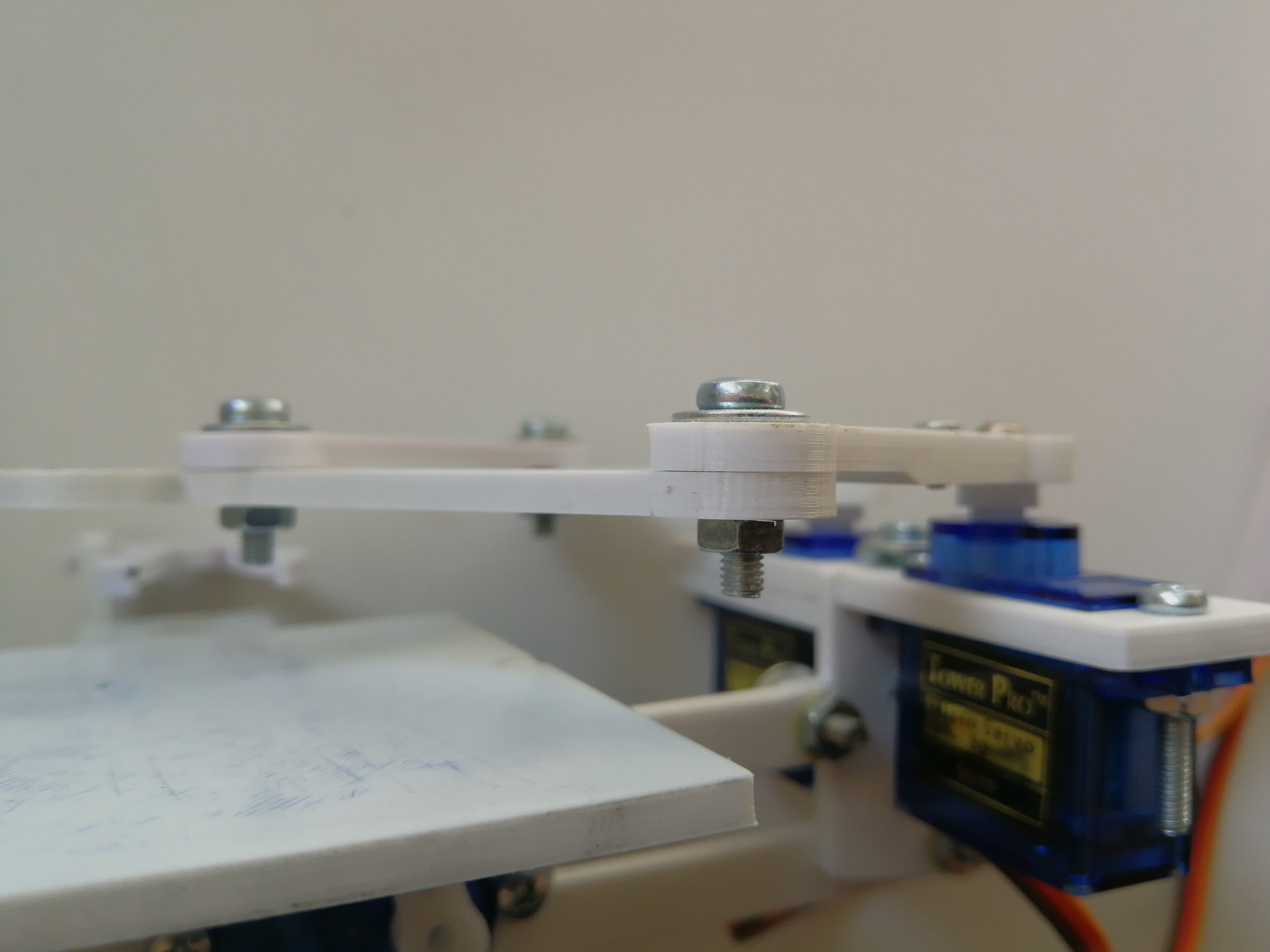
Next, without rotating shafts, attach servo levers to servos exactly as on the pictures below. After that you can rotate servo shafts as you want and join printed levers.
When joining levers using screws and nuts, glue nuts to levers to prevent them from loosening.
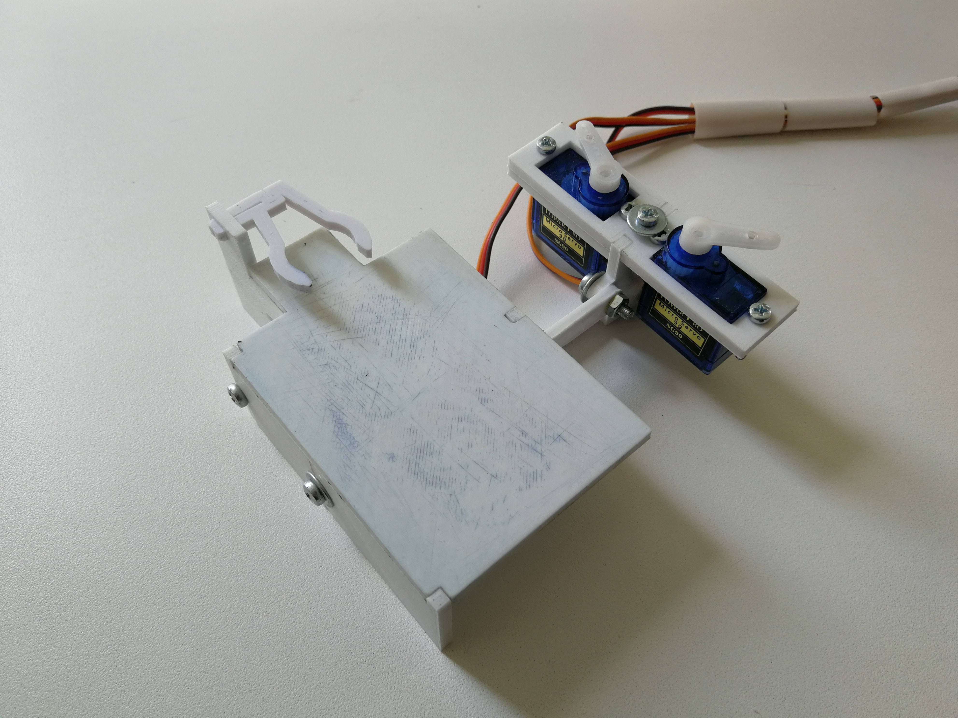
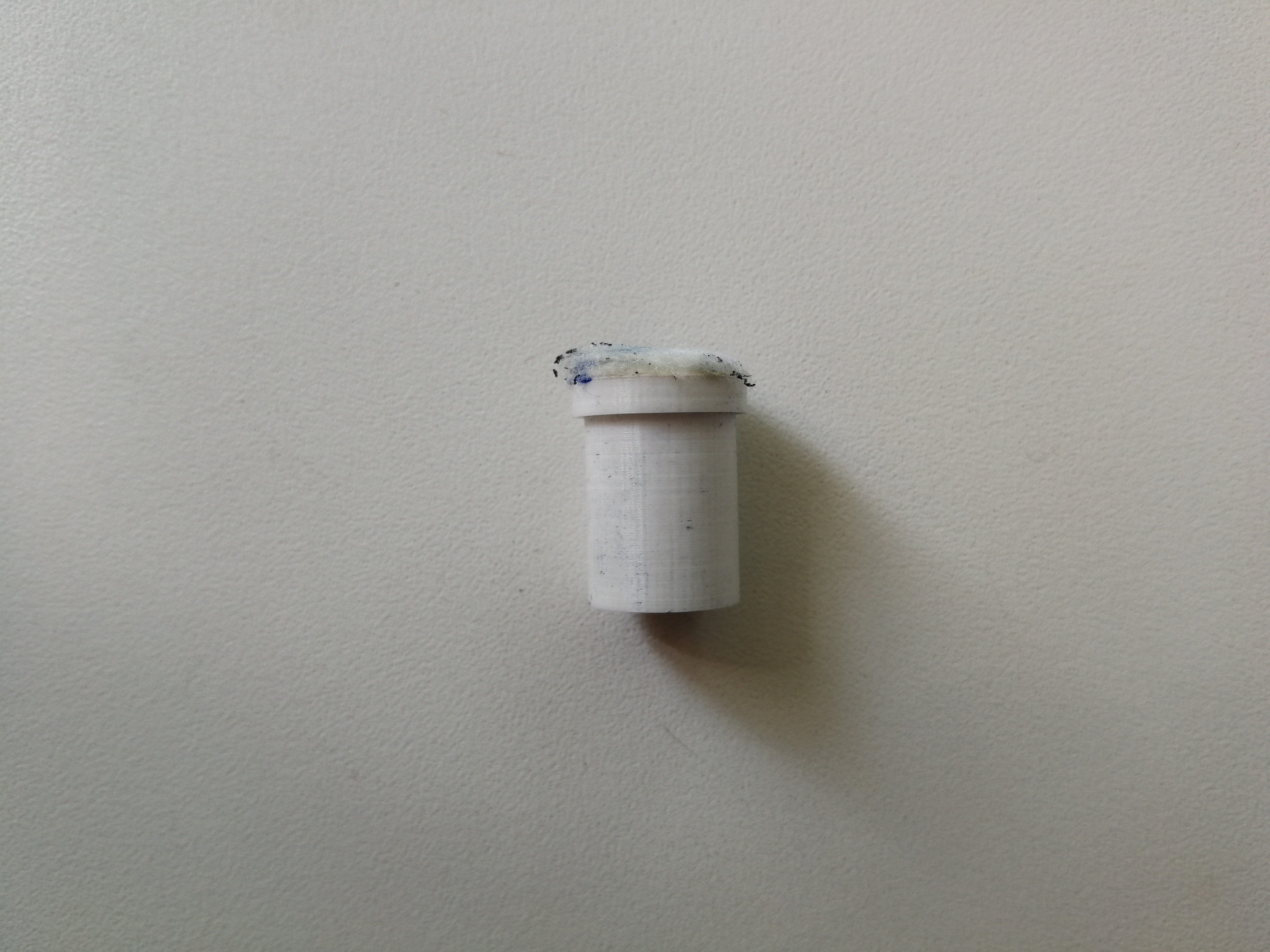
Glue a piece of either cloth or cotton to eraser.
- Solder both of pin headers into ChronoDot v2.0 RTC module.
- Solder both of resistors into the module.
- Install CR2016 battery on the module.
Put 12V into the LM2596S voltage regulator and adjust it down to make an output voltage 5.5V.
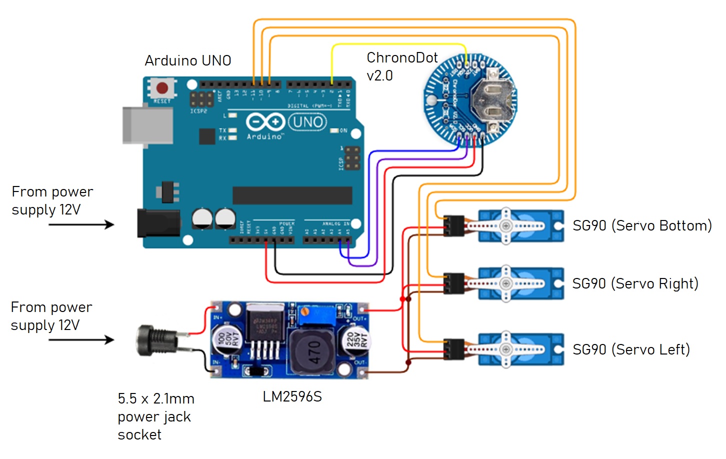
Connect all the modules together according to the wiring diagram below.
To prevent PCBs from moving make something kind of platform or box for them and fix PCBs on it with screws and nuts.
Sketch and its dependencies are located under plotclock_code directory.
Copy all the libraries from plotclock_code/libraries directory to your machine's Arduino libraries directory. Now you are ready to compile and upload the sketch.
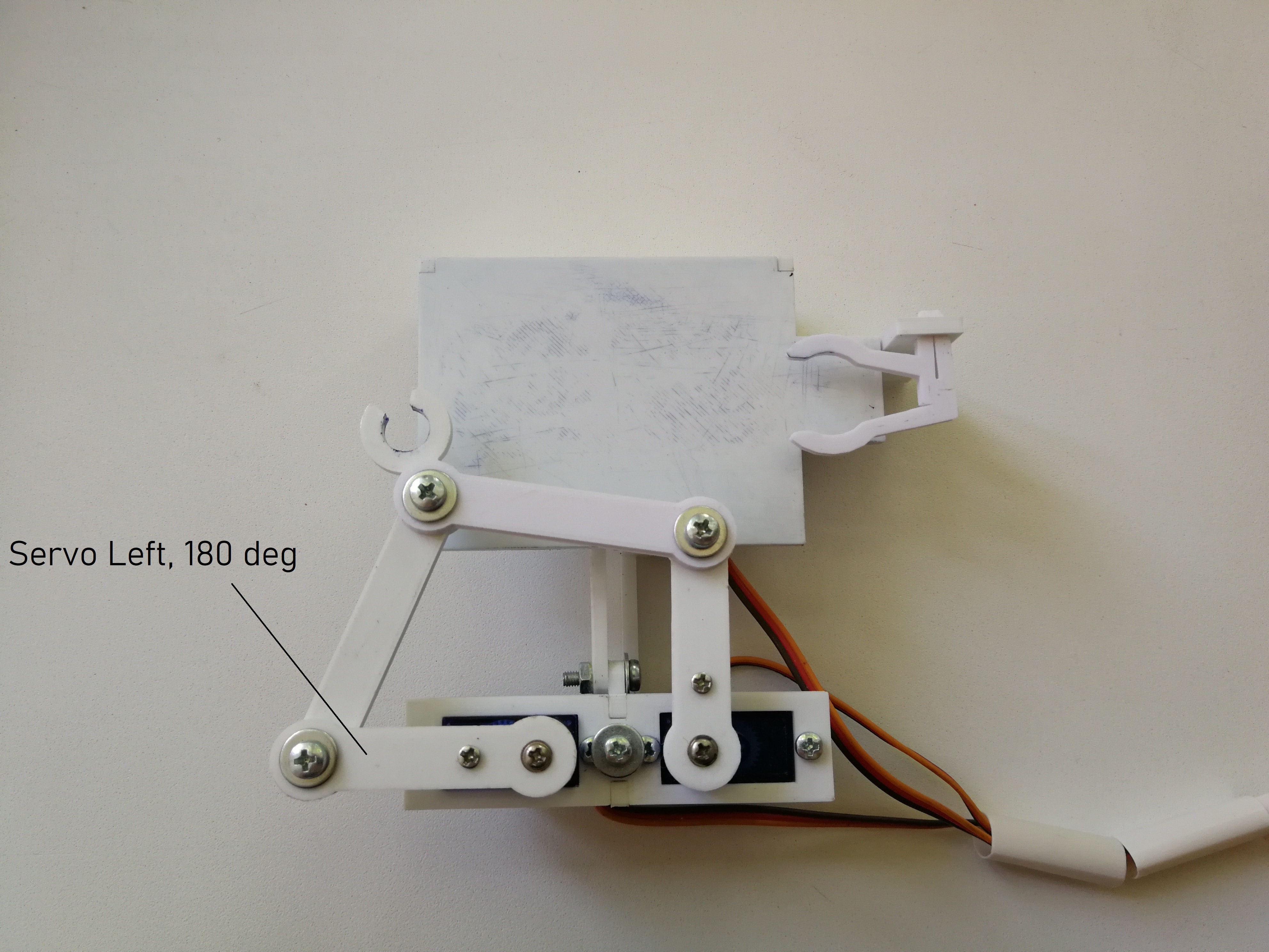
To be sure marker is positioned correctly you should calibrate servo values for some predefined positions. Set appropriate values for the following macros in the sketch:
SERVO_LEFT_ANGLE_180- left servo value when its lever rotated 180 degrees and is parallel to the board;SERVO_LEFT_ANGLE_90- left servo value when its lever rotated 90 degrees and is perpendicular to the board;SERVO_RIGHT_ANGLE_0- right servo value when its lever rotated 0 degrees and is parallel to the board.
This lever positions are shown in pictures below.
To calibrate Z-axis marker positioning, change the following macros of bottom servo values:
SERVO_BOTTOM_PV_WR_BOTTOM- position of marker when it touches the board and chars becomes written;SERVO_BOTTOM_PV_WR_UP- position of marker to move it between chars without writing a line;SERVO_BOTTOM_PV_ERS_BOTTOM- marker is in the eraser;SERVO_BOTTOM_PV_FULLUP- marker is above the eraser.
After calibrating and uploading the sketch the robot can be considered fully assembled and good to go. Since RTC module contains the battery you don't have to reupload the sketch whenever you turn the power off to setup the actual time - the module keeps track of it by itself.
This section describes provided solution for drawing figures and intended to help you to deal with sketch and customize it if necessary.
To move marker to specific point of the drawing plane you have to rotate servo shafts by specific angle. In order to draw a char you have to perform a series of movements to different points; for each of them you have to know rotation angles for both servo left and right shafts.
To provide an ability to move the marker by specifying position of point but not the rotation angles, virtual coordinate plane was defined. The origin of the plane is located relative to the servo shafts axes, and it's position is configurable.
Plane lines unit is millimeter. It thus allows you to understand the physical location of particular point without additional units conversion.
This coordinate plane is shown on picture below. Blue, red and green colors indicate the corresponding parts of the 'arms' lever system (top view) for one of the possible marker positions. Point D here is a marker position, and points A and B indicate servo shafts axes. The AK distance is equal to the length of the AF lever. Distances OL and LN are customizable and added to provide ability to configure origin position.
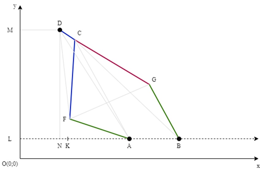
Since all of the valuable distances between points are known and distances MD and DN can be calculated from provided x and y coordinates, it is possible to calculate the angles FAB and ABG that represent either angles of the servos or those from which they can be obtained (servo left angle = FAB, servo right angle = 180 - ABG).
Algorithm to find these values is implemented in getServoAngles
function. To move the marker use moveTo function. It uses
getServoAngles within itself.
Since coordinate plane is defined, you can describe any figure you want with a function. And, as soon as you define a function, you can draw this figure by iterating over axis values, passing these values to a function and thus getting the coordinates of points that outline of figure consists of.
Exactly this way all chars becomes drawn. But, in order to simplify functions, chars are described as a set of primitives. These are lines, circles and ellipses.
For example, number '1' consists of 2 lines, while number '8' is 2 ellipses. Hence, to draw these numbers the robot sequentially draw their primitives.
Due to design features, not all of the board surface area is available for drawing. For current design all the points that the robot can positions is shown on picture below.
This area is indicated in red. The board is located according to its actual location. Black rectangle indicates the max area determined for drawing chars.
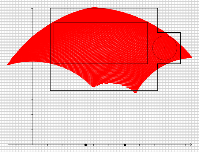
Take this information into account if you want to customize chars, positions or sizes, or if you going to draw your own figures.
You can find editable models of the robot components under plotclock_details/kompas_models directory.
The project also provides a tool to show available drawing area (described above) for a specific design setup. This tool is located under plotclock_design directory and can help you determine sizes or positions of different components for new design and define drawing area boundaries.
SG90 are pretty chip servos and cannot provide guaranteed ability to rotate their shaft by an angle lower then ~0.75 degree under the marker weight. Therefore quite big positioning errors occur. As a result there are jagged lines and currently no ability of physically accurate positioning.
To solve it, more accurate and expensive servos should be used to give an ability to rotate shafts by at least 0.1 degree.
Thanks to joo from Thingiverse for idea and initial design of components. See original project here.