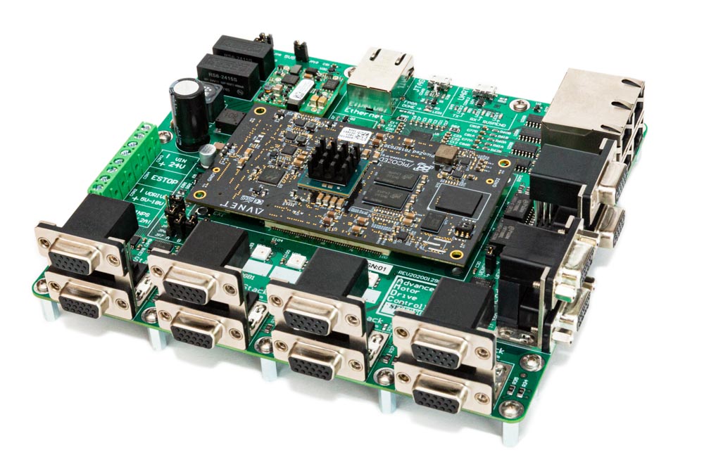
The Advanced Motor Drive Controller (AMDC) is an open-source project from the Severson Research Group at UW-Madison, affiliated with Wisconsin Electric Machines and Power Electronics Consortium (WEMPEC).
Learn more at docs.amdc.dev.
AMDC-Hardware is a collection of circuit board designs which are used to control advanced motor systems. The hardware design is open-source, modular, and research-oriented.
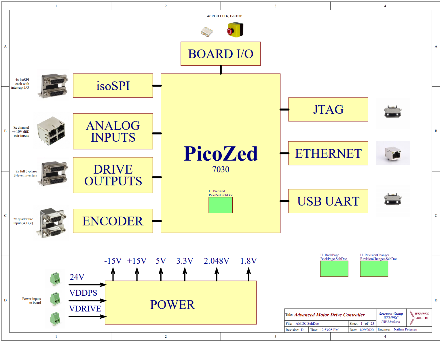
The flagship circuit board is the main AMDC (see latest design here) which is a carrier board for the PicoZed System-on-Module. The PicoZed is a module itself which contains the core requirements for the Xilinx Zynq-7000 System-on-Chip. The Xilinx Zynq-7000 SoC is a powerful processor with dual-core DSPs and a tightly integrated FPGA.
Extensive firmware support is provided in the AMDC-Firmware repo which targets this architecture.
The altium directory contains all files pertaining to schematics / board design in Altium Designer. These files should be the latest working copy of the project.
The REVyyyymmdd* directories represent snapshots of the project that were used to produce a physical PCB. These directories contain the Gerber, Drill (Excellon format), Bill of Materials (CSV), and Schematic (PDF) files.
REVindicates a revision of design for manufacturingyyyymmddindicates the date on which design was frozen*(letter) indicates which revision in sequence (A - first, B - second, etc.)
Numerous accessory circuit boards are designed to work with the AMDC (e.g., DAC, TestBoard, CAN expansion, I/O expansion).
These are located in the /Accessories/ subfolder. Each accessory board follows the same repo set-up conventions as desribed above for the main AMDC.
The AMDC is designed for research environments where flexible and plentiful I/O are required.
The provided interfaces include:
- 48 digital output channels (designed to provide PWM signals for 8 three phase, two level inverters)
- 8 analog input channels (+/- 10V differential input)
- 4 GPIO expansion ports (differential I/O)
- 2 quadrature encoder input
The AMDC-Hardware project is open-source -- contributors are welcome!
The REVxxxx/ output folder contains the compiled design files needed to order hardware:
- Review the board design using the 3D renderings and the schematics PDF
- Check the
docs/folder for any imformation about the board design - Order PCB blanks using the gerber files in the
REVxxxx/gerbers/folder and the specs provided in theREADME.mdfile - Order components using the BOM file provided as CSV
Note: all board designs are created using Altium Designer -- a license is required to design boards for the AMDC-Hardware project.
The altium/ subfolder contains the latest design files for the board.
Detailed documentation about the hardware is available online at: docs.amdc.dev/hardware.
The documentation explains the design narrative and process, design choices, requirements, relevant equations and diagrams, etc.
This project originated as Nathan Petersen's Independent Study project during Spring 2018, advised by Prof. Eric Severson. It is now actively maintained by the Severson Research Group. Open source firmware is available on GitHub in the AMDC-Firmware repository.

