This is library intended to use with radio modules based on bk2421/bk2423/bk2425 chips, commonly known as RFM70/RFM73/RFM75 or even more other rebrands like LCX24A(G?), TRW-24G2, SQI73/SQI75 and of course "not working" nrf24l01+ (cob) fakes. Also rare chips like bk2411/bk2412/bk5811 are also supported.
In order to force those modules to work as intended, special (undocumented of course) initialization sequence have to be followed:
- All "reserved & read-only" status registers in
BANK0have to be initialized - otherwise communication doesn't work after some power cycles (covered byrfm7x_init()) - BANK1 registers have to be initialized with predefined undocumented magic values which are different among datasheets for the same chip. (covered by
rfm7x_init()) - All reserved registers in
BANK1have to be initialized. (covered byrfm7x_init()) - After power-up 1 or 2 bits in reg4(
BANK1) have to be toggled. It might be necessary even after every power-up. (covered byrfm7x_toggle_reg4())
Every time the transmitter hits 15 retransmissions limit (no ACK received from called slave), MAX_RT interrupt request flag have to be cleared.
Unlike the nRF24/SI24R1, in bk242x it is not enough, because PLOS_CNT is "overflow protected".
In this case FLUSH_TX command have to be also executed, to unlock any further transmissions. (covered by rfm7x_mode_transmit())
- All documentations says about 83 available channels, but tests show that all 127 channels can be used. (of course, only when you are allowed to use those)
- All modules except bk2425 (rfm75) are said to be 5V (IO) tolerant "but that's not the case".
- Other minor differencies can be found in rebranded application notes
In almost all nRF24 fakes, any kind of power noise, missing decoupling, or even anything around within few meters, may result in increased packet drop rate. Even though properly initialized bk242x chips are more stable than SI24R1, it still requires additional bypass caps.
Usually the exact fake model can be determined by exploiting specific features (including register dups), comparing overall module design or measuring current consumption. The following function should reveal any bk242x and SE8R01 (the one with only 3 components except cob and oscillator, not compatible) chip:
uint8_t rfm7x_is_present(void)
{
 	uint8_t tmp1, tmp2;
 	tmp1 = rfm7x_reg_read(RFM7x_REG_STATUS);
 	rfm7x_reg_write(RFM7x_CMD_ACTIVATE, 0x53);
 	tmp2 = rfm7x_reg_read(RFM7x_REG_STATUS);
 	rfm7x_reg_write(RFM7x_CMD_ACTIVATE, 0x53);
 	return (tmp1 ^ tmp2) == 0x80;
}
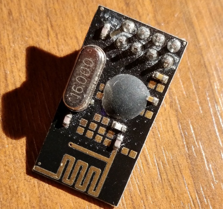
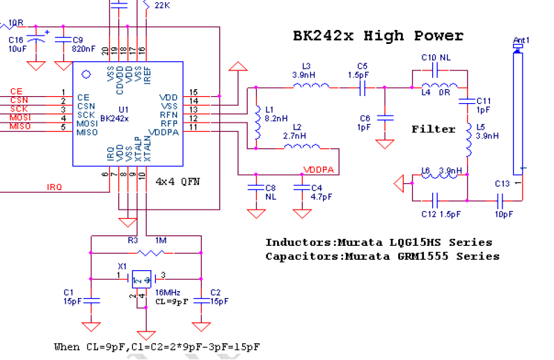
This is one of the most chinesed nRF24l01+ clone. It is assumed to be SI24R1 and always opens discussion about legality of missing RF filtering, but after some testing it turns out to be ordinary bk2425. If we look at schematics, there is not much missing:
 left side from: https://ncrmnt.org/2015/03/13/how-do-i-cost-optimize-nrf24l01/
The re-marked nRF24L01P (+) clones are not 100% register compatible. The issue with the counterfeit devices is that when they enabled “Dynamic Payload Length” (EN_DPL) in the "FEATURE" register, one bit get’s activated in the on-air payload (the NO_ACK bit) This bit should be active high (according to the Nordic datasheet), but it’s actually implemented the other way around. When EN_DPL is activated, the NO_ACK bit get reversed in the real nRF-devices. They did such a good job of cloning they cloned the datasheet error into the device!!!
Inversion of NO_ACK bit in the air payload can be controlled by the undocumented compatible mode bit in one of the bank1 registers.
It can also be changed with simple RFM7x_CONFIG_COMPATIBLE_MODE macro in config header.
- To communicate with SI24R1, it have to be set into
static compatiblemode - Otherwise
dynamic compatiblemode is recommended (genuine nrf?)
AN0007 describes "non-existent" settings for high power/current mode in bk2423 (rfm73).
It is said to output up to 15 dBm and require additional low-pass filter to pass FCC tests.
bk2425 seems to not include this feature.
| current in normal mode | current in high power mode |
|---|---|
 |
 |
Standalone RFM's were not weird enough so the 'P' version was introduced.
- RFX2401C datasheet specifies +5 dBm input power as ABSOLUTE MAXIMUM, but saturation output power is +22dBm
with 25 (28 for RFX2402E) dB of 'small signal' gain, so it expects 0dBm or even less of TX power ("chinese replacements" might have similiar limits)
high powermode in bk2423 is not allowed here.- if module can't communicate for longer distances (usually more than 5 meters), try lowering power levels, even down to -20dBm.
- in my tests anyting above -1/0dBm was highly unreliable
- HOPERF claims that their "chinese replacement" of RFX ?? works up to 4.2V, although RFAXIS reccomends typical 3V3 operation, with 4.0V (4.5V for 2402E), as an ABSULUTE MAXIMUM. It is reported that the PA doesn't work correctly above 3.6V source
- Auto ACK is not possible since TREN (TXEN) signal is broken out on header instead of connecting it to the VDDPA output.
Those modules requires hardware modification to act as a regular rfm7x with auto retransmissions and ACK. It has been done back in 2013 here.
- PAEN (RXEN) have to be connected to CE line, like in cheap nRF+PA modules, since RFX treats it as "doesn't care" in TX mode (10us single shot transmissions should be possible)
- VDDPA (between C3,L2) have to be conected to TREN (TXEN) input of RFX through onboard 1K resistor.
- It is recommended to use >0.47uH inductor for direct connection to (VDDPA)RF path (the existing 2.7-12 nH seems to be too low for even 10x impedance ratio).
This module uses bk2425 chip which is a (BOM) cost optimized one, thus it doesn't have VDDPA output. Internal PA seemed to leak some DC offset into antenna path, so it could be somehow possible to extract TREN (TXEN) signal.
- PAEN (RXEN) have to be connected to CE line, like in cheap nRF+PA modules, since RFX treats it as "doesn't care" in TX mode (10us single shot transmissions should be possible)

