Python3 based QGIS3 plugin for Line of Sight Analysis to support UAV mission planning
For installation of the plugin simply download this repository as .zip file and then install plugin via .zip in the QGIS3 plugin menu. If you are interested in the used methods, please have a look at los_analysis.py, as this is where all the computations happen. The rest of this readme is about the purpose of the plugin and instructions/recommendations of its use.
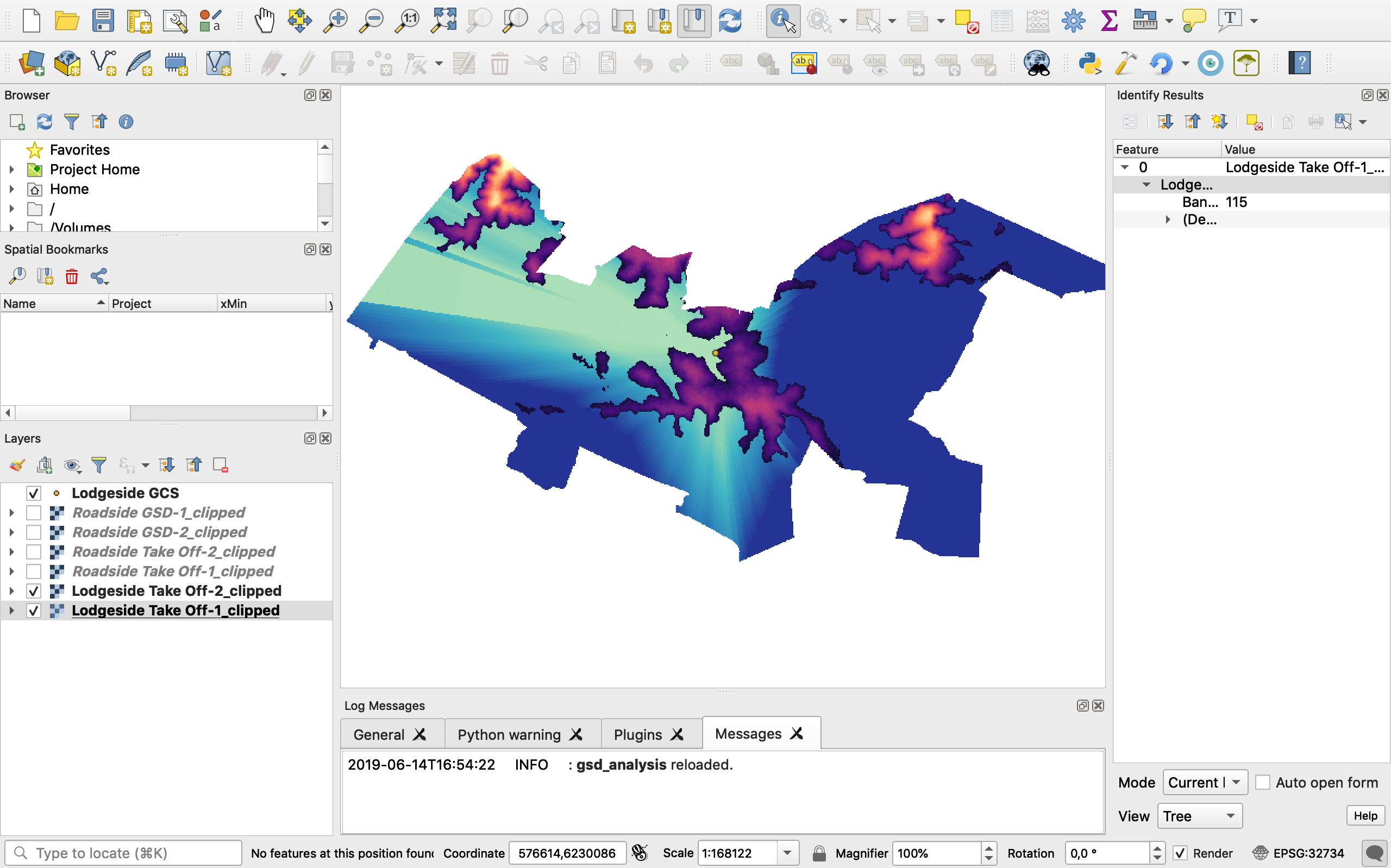
Legend:
- Ray-like raster displays the required flight altitude (darker -> higher) w.r.t. take-off in order to maintain (Radar) Line-of-Sight.
- Overlayed irregular features show terrain that is at higher altitude than take-off and therefore drives the required flight altitude.
Flight planning over mountainous terrain is not straightforward. The choice of ground station/ take-off location has great impact on the success of the mission. It is not sufficient to simply make a decision from the gut and especially when the ground station location has to negotiated with authorities, it is helpful to be able to support your position with some sort of analysis. This is where the QGIS plugins Line of Sight Analysis and GSD Analysis can be valuable tools. They enable to analyse the terrain of operation from the office which saves time in the field and can be used to convince authorities of the benefits of a desired take-off location.
This plugin (LosAnalysis) enables advanced Line-of-Sight computations accounting for atmospheric diffraction and Fresnel Zone clearance. As a bonus the results look super awesome… Have fun!
- Have a working version of Python 3.6 installed on your system (Python 3.7 was not compatible with QGIS at the time this was written)
- Have a working version of Quantum GIS3 (QGIS3) installed on your system
- Test if QGIS and Python synergise (for example by importing modules in the QGIS Python Console ) if not seek help from the PyQGIS Community
Part 0: Install the Line of Sight Analysis Plugin
- Download the full repository as .zip file
- Open QGIS. Go to Plugins (Title Bar), select Manage and Install Plugins and choose Install from zip. Upload the .zip file and Install Plugin.
- Reopen QGIS. Go to Plugins (Title Bar) and check if the installation was successful. You should see the Line of Sight Analysis Plugin in that menu.
- Go to https://vertex.daac.asf.alaska.edu.
- Click on Earthdata Login on the right of the top menu bar, login in or go through the sign up procedure. After you have signed up and you are logged in you can continue.
- Select your area of interest by drawing a rectangular box/ polygon on the map. Under Dataset uncheck all boxes except for ALOS PALSAR (ALOS is the Jaxa Satellite carrying the PALSAR instrument doing the radar measurements). Start the Search.
- The matching results will appear in a menu to the left of the map. Select the tile that say ALOS PALSAR FBD (FBD = Fine Beam Dual Polarized). Click on Details. This will open a Dialog with the option to download our desired product: The High-Res Terrain Corrected.
- Download the file. In your downloads directory you will find a folder that starts with something like AP-…, containing (amongst others) 3 tif files: HV, HH and DEM. The DEM file contains the terrain corrected elevation model.
- Open QGIS.
- Set Project CRS (Coordinate Reference System). Go to Project (Title Bar) --> Project Properties --> CRS, enable ‘on the fly’ CRS transformation. Then choose your CRS. I recommend W84
- Upload your DEM into the QGIS Project via Add Raster Layer (left menu bar). It might appear not so nice, but that is ok for now (unless you want to explore and verify the elevation data before the analysis, in which case you should have a look at styling your layers)
- Upload available infrastructure files through Add Vector Layer (left menu bar), such as fencelines, roads, gates or other landmarks.
- If not part of the Infrastructure shapefile, create your take off location. In the top menu select Layer --> Create Layer --> New Shapefile Layer (or on the left menu bar). In the Dialog select Type: Point, make sure the layer CRS is coherent with the rest of your project. Click Ok name your layer and chose a directory. Once the layer exists, it will appear in the legend of your project.
- Select the new vector layer in the legend. Then click on the edit icon in the top left to make the layer editable. Then choose the icon (to the right of the edit icon) and add a point to the layer by a click on the map. Then untoggle the edit icon again.
- Navigate to the Plugins menu (Title Menu), choose the Line of Sight Analysis plugin. Provide full (unclipped) DEM and the shapefile that contains your take-off location, the other options should be straightforward. Note that the plugin can’t handle, when the area of interest (defined by GCS location and radius of interest) extends beyond the domain of the DEM, on which the calculations are based. To clip the resulting Line of Sight map, upload a shapefile that can be used as a mask for clipping operations.
- Run the analysis. After the process is complete, you will find the following files in your directory:
- /filename-0.txt: Contains the chose parameters
- /filename-1.tif: Minimum flight altitude w.r.t. GCS for LoS
- /filename-2.tif: Terrain elevations above GCS
This shows that the actual analysis results are contained in the -1.tif file. The -2.tif file provides information that directly lead to the result. The plugins outputs the -2.tif files to give the user the possibility to visualize the causes of the final result and to convince of its correctness. The -0.txt file is to document the user input parameters, such that the results contained in the corresponding .tif files can always be linked to the exact conditions under which they were produced.
The results of the analysis are directly uploaded to your QGIS project instance. You will find them in the legend on the left and they should be visible in the canvas. The layers are added in a predefined style, that enables direct visual comparison of results. Styles are chosen for nice visualization within the relevant domains, however since these may change from case to case, you can always change them in the Style menu of the layer. This menu is part of the layer properties, which you can access by double clicking on the layer’s legend entry. If you want to change the predefined style with which the layers are automatically added to the project instance, you can save the desired style as .qml file and place it in the plugin directory. Now replace the second argument of the addToInstance method in the last lines of the analysis.py file with the name of your .qml file and voilà.