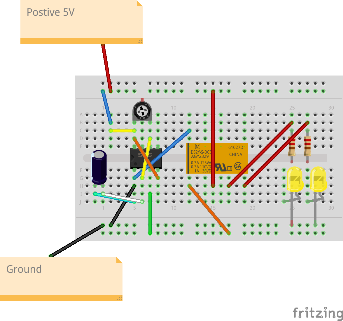
Desk Art
Key features of your breadboard project.
- If you implement this circuit you will have a set of leds tick/tock flashing back and forth.
- The speed (and if they flash at all) is controllabled via the trimpot and up to you.
- Fun
- Hypnotic
- Inspiration for decision making
Materials required to replicate the project:
- 555 Timer
- 5V Relay
- 2 x 220 Ohm R
- 2 x yellow LEDs
- Some jumper cables
- 10 k TrimPot
- 400 point breadboard
(All available at jameco.com or other electronics online stores)
How to set up the breadboard project.
| 555 Pin | Name | Description |
|---|---|---|
| 1 | GND | Ground. Connect to the ground reference of your circuit. |
| 1 | GND | Jumper this to the Relay's input/coil |
| 1 | GND | Jumper this to 10uf Capacitor (or place in line) |
| 2 | TRIG | Jumper this to Pin 6 |
| 2 | TRIG | Jumper this to 10uf Capacitor (or place in line) |
| 3 | OUT | Jumper this to the outer rail |
| 4 | RESET | Jumper this to Pin 8 |
| 5 | CTRL | Leave Alone |
| 6 | THR | Already jumpered to Pin 2 |
| 6 | THR | Keep in line with right leg of TrimPot |
| 7 | DISCH | Keep in line with middle leg of TrimPot |
| 8 | VCC | Keep in line with left leg of TrimPot |
| 8 | VCC | Connect to 5V VCC |
| Relay Pin | Description |
|---|---|
| Common | Connect to +5V power |
| Common | Optional - Connect to second +5V power for a more elaborate effect |
| Coil | Connect to outer rail (shared with Pin 3 of 555 timer) |
| NO | Connect to LED |
| NC | Connect to LED |
| LED | Description |
|---|---|
| Cathodes | Connect to resistors |
| Anode | Connect to GND |
(See /images for pdf, fzz and others)

