A USART master-slave setup for the Atmega328p through a differencial communication, the LTC485. Uses 9bit, 1 stop bit and odd parity and Multi-processor communication mode (MPCM). Includes a printable PCB and code.
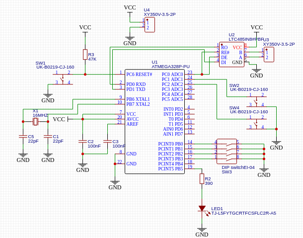
Includes an ATmega328p, an LTC485, a crystal oscillator clock, 4 switches, 2 buttons, and some external ports as screw terminals. It is seen in the next schematic designed in EasyEDA.
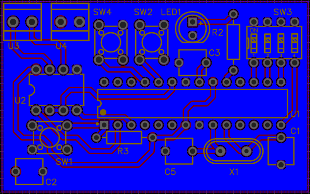
The PCB that was produced from it:
void transmit(uint8_t isAddress, uint8_t data);Waits for the "USART Data Register Empty" bit to be true and sets 9th bit to either 1 (if packet is an address) or 0 (if packet is data), and remaining bits to UART buffer.
uint8_t receive(){Waits for the "USART Receive Complete" bit to be true and set received data to a global variable (rxData) and returns whether if received an address or data frame.
void initUSART(uint32_t baud, uint8_t isTX){Sets baud rate, 9-bit dataframe, 1 stop bit and parity, in case of slave, turns on Multi-Processor Communication Mode. Being TX means being a master and not being TX means being a slave.
void setup(){Sets needed pins for pullup and sets led pin and tx line to outputs. Reads address of switches and sends result to previous function. Stores address in global variable.
void slaveLoop(){Infinite loop that waits to receive a message. If message is an address, and if the address received matches the receiver, the receiver disables MPCM to wait for a data frame. If message is data, knowing it will only arrive if the receiver has been addressed before, it will either set or clear the pin of the led.
void masterLoop(){Infinite loop that polls for a pin value change in the button pins. When one is detected, an address frame is sent to the button that represents the slave, and a data frame to either turn on or off the led.

