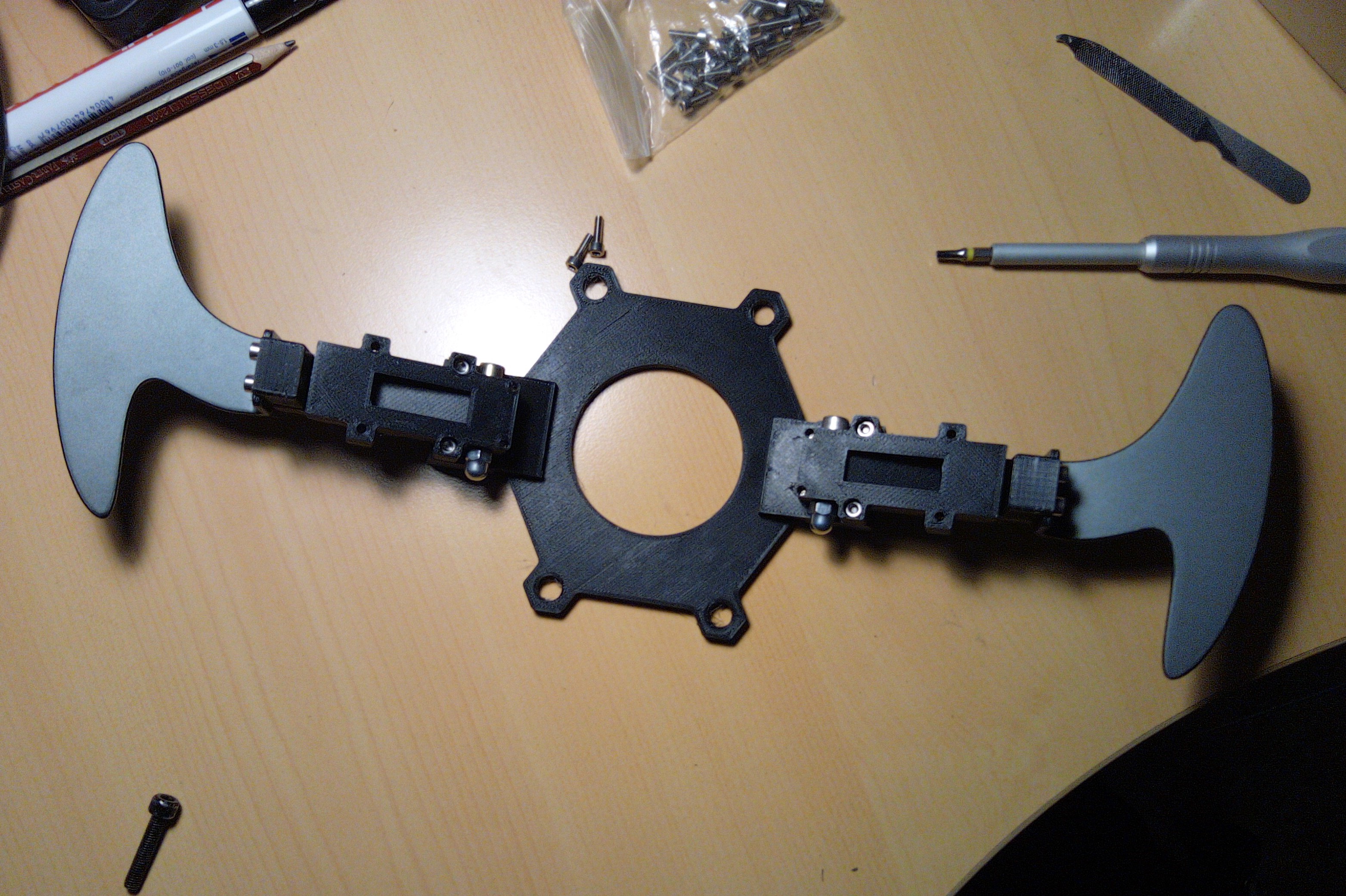
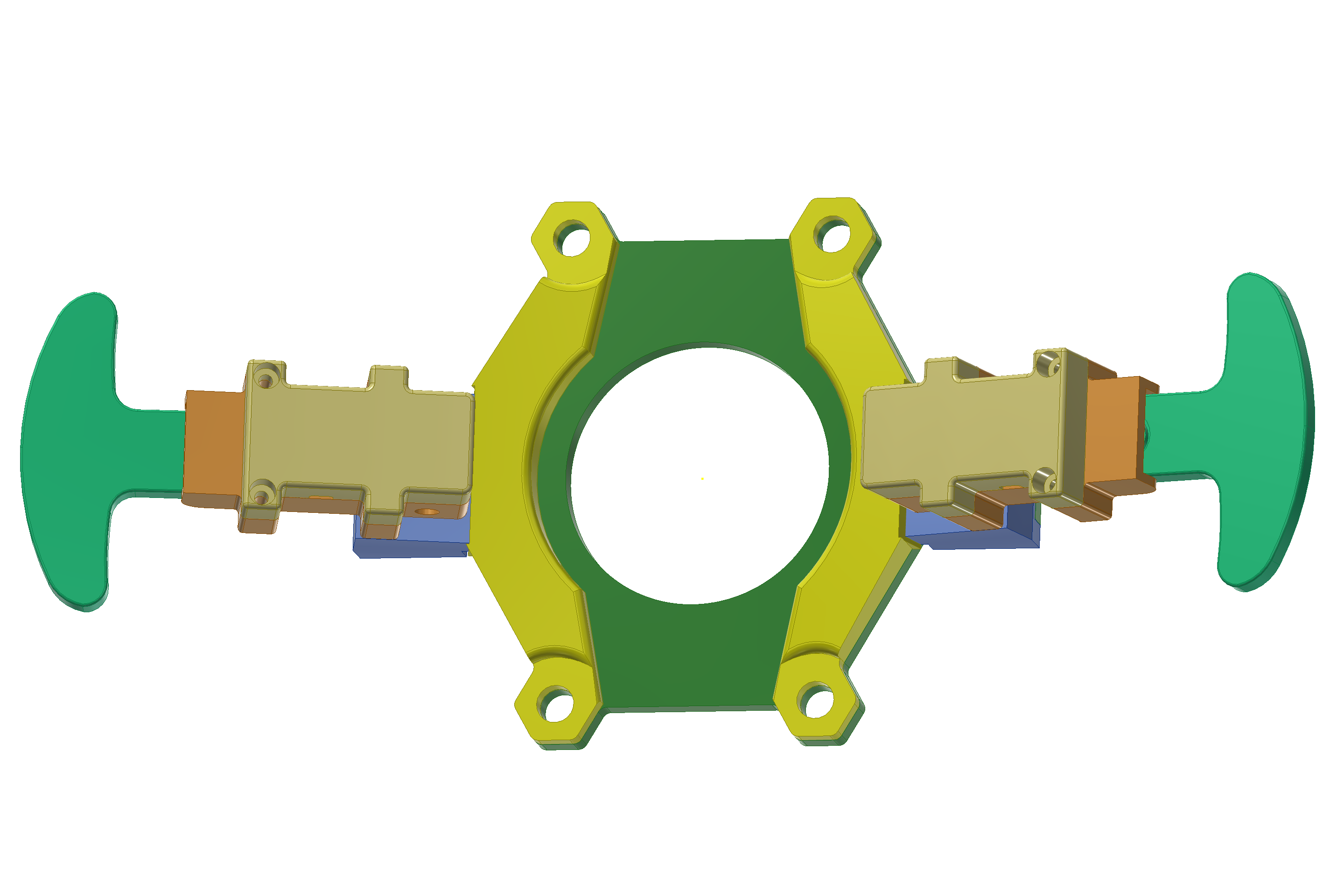
Project about how to connect shifters (sequential or H-shaped) on Fanatec Wheel bases, using it's internal protocol. Tested with a sequential shifter on CSL elite 1.1. Also the 3D models for the Levers and electronics are provided. In this example, we can connect directly our shifter levers to port Shifter2 (rj12) also works on Shifter1.
The problem is simple: interface the wheel base so we can send two signals, gear up, and gear down. Fanatec sells static paddles, a fully H-patter shifter, and also a sequential shifter. Some wheels include the shifters, also (as my BMW GT2 wheel). The problem with that wheels in that the paddles moves along the wheel, so in tight turns (aka rally) you can't reach the paddles.
- Fully printable, so you can download the project, start your printer, and print all the parts. The STL are ready to print, so the orientation and tolerances are configured and tested.
- Uses the standard RJ12 port with it's internal protocol, so just plug and play.
- Cheap to build. Based on standard hardware components:
- Printed on PETG
- Some wiring cable (8 wires)
- 30 allen screws (13mm)
- 4 allen screws (6mm)
- 2 allen screews M4 (24 mm) for lever axis
- 2 standard micro switch NO
- a RJ12 to RJ12-6p6c (all poles connected, 1-1) cable, to do the wiring.
- 2 springs for the levers.
All the parts are designed on Autodesk Inventor 2019. I provide the STL files. Printed on a Creality Ender-3 Pro, with BQ PETG. These are the CURA settings for all the parts printed:
- Layer Height: 0.2
- Wall Thickness: 0.8
- Top/Botton Thickness: 0.8
- Top Layers: 4
- Bottom Layers: 4
- Infill: 60%, Grid
- Printing temperature: 220 ºC
- Build plate temperature: 80 ºC
- Speed: 50 mm/s
- Cooling: Enable
- Fan Speed: 100%
- Enable supports: Everywhere
- Build Plate adhesion: None
Note that all the parts are sturdy and the print time is about 3 hours for the plate. Let the printed print. Check that the nozzle in clean (run small batches) because the PETG is very sticky and stringy.
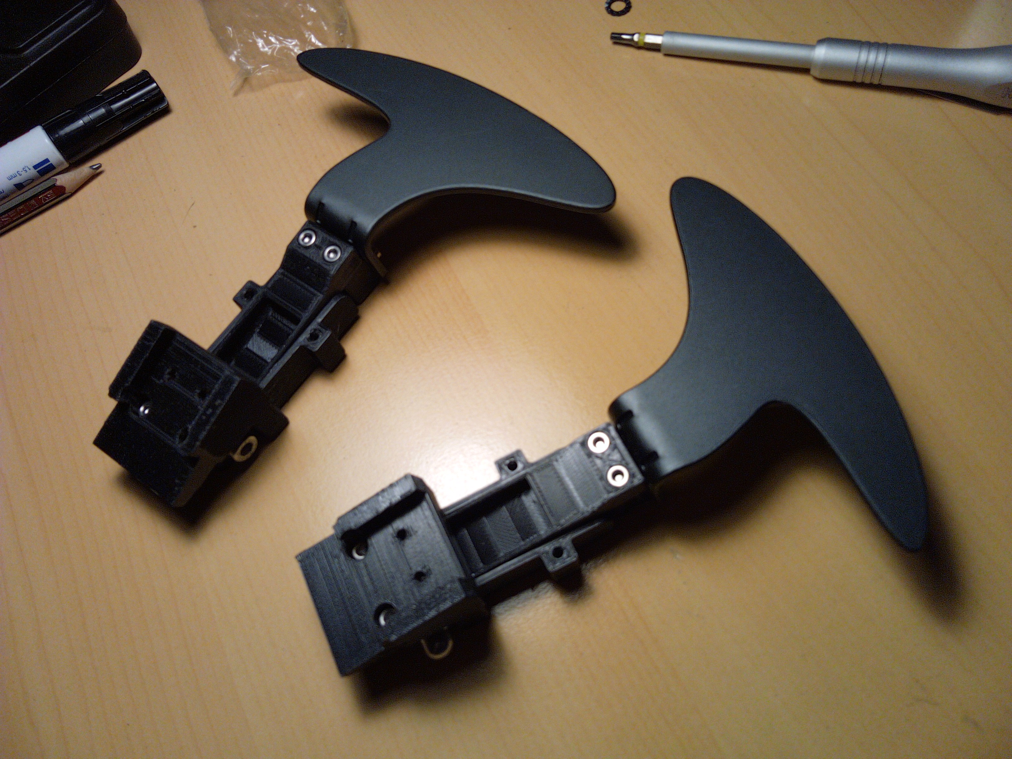
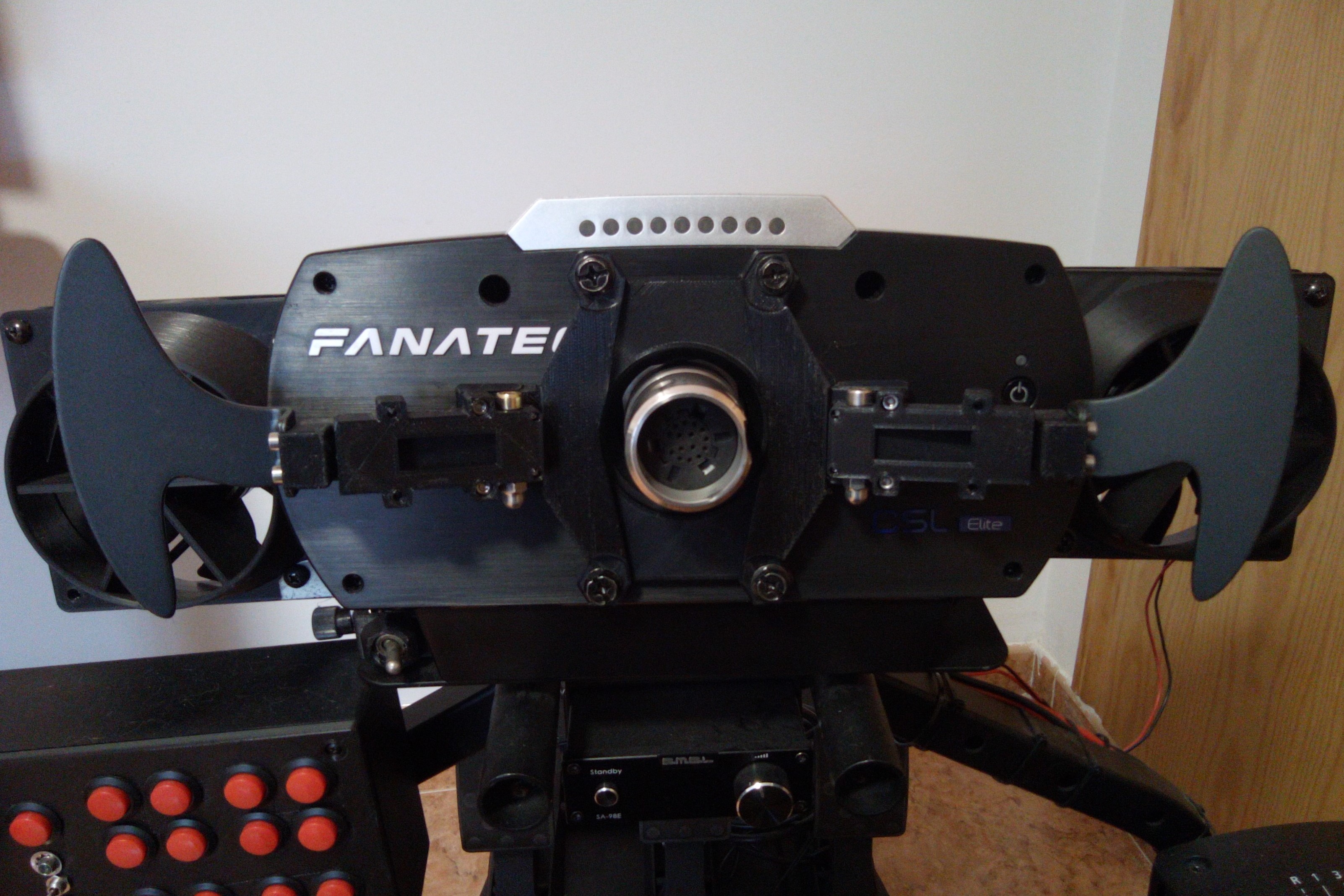
This is the base plate where the parts are mounted and touches the wheel base using the screws. This plate is created for the CSL-Elite 1.1, so be careful that hole position can change in CSL 2.5 or podium bases. Print it sturdy and slow to avoid bending when using the levers. About 3 hours to print.

This reinforcements (2x) are mounted at each side, pressing the levers with the plate, to avoid bending.
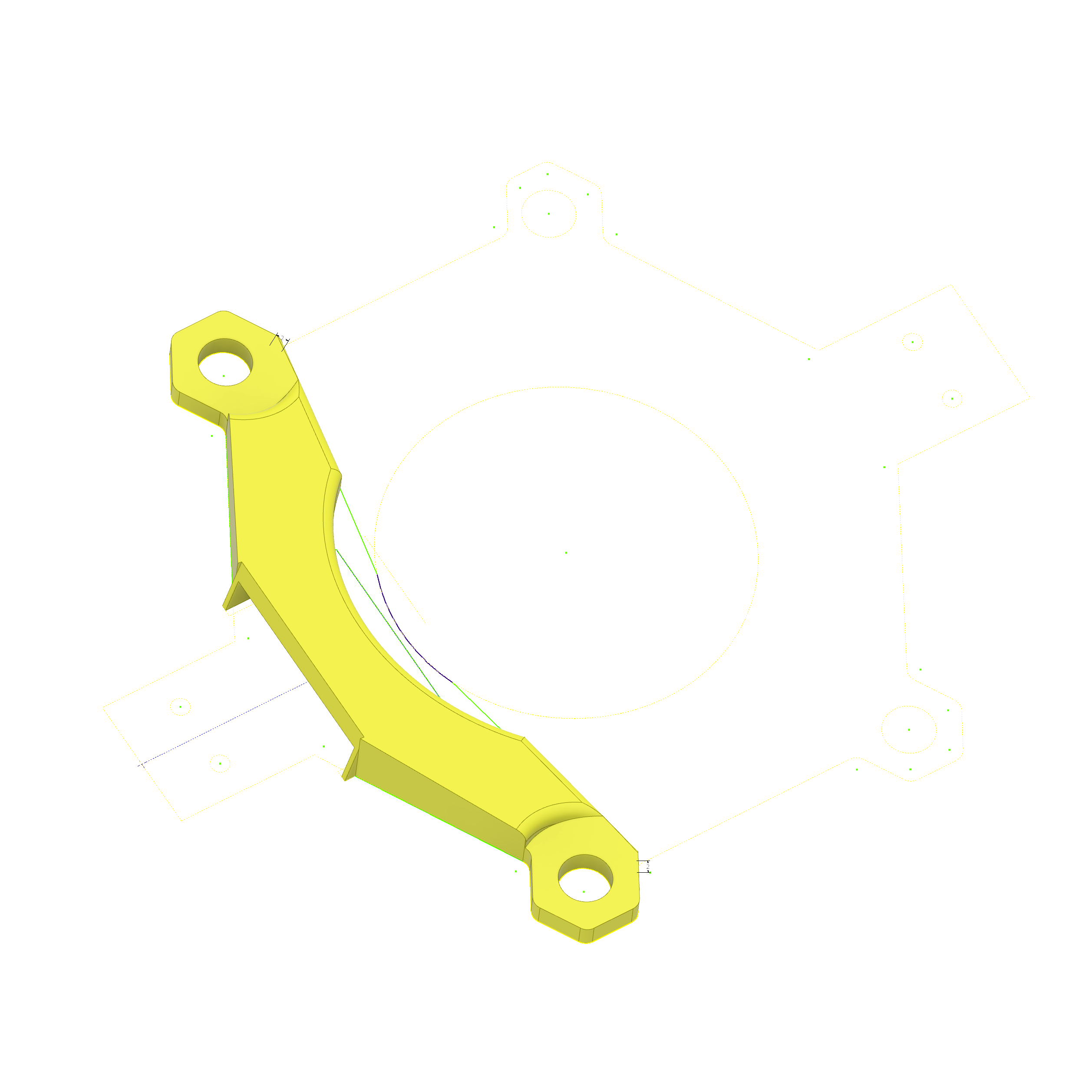
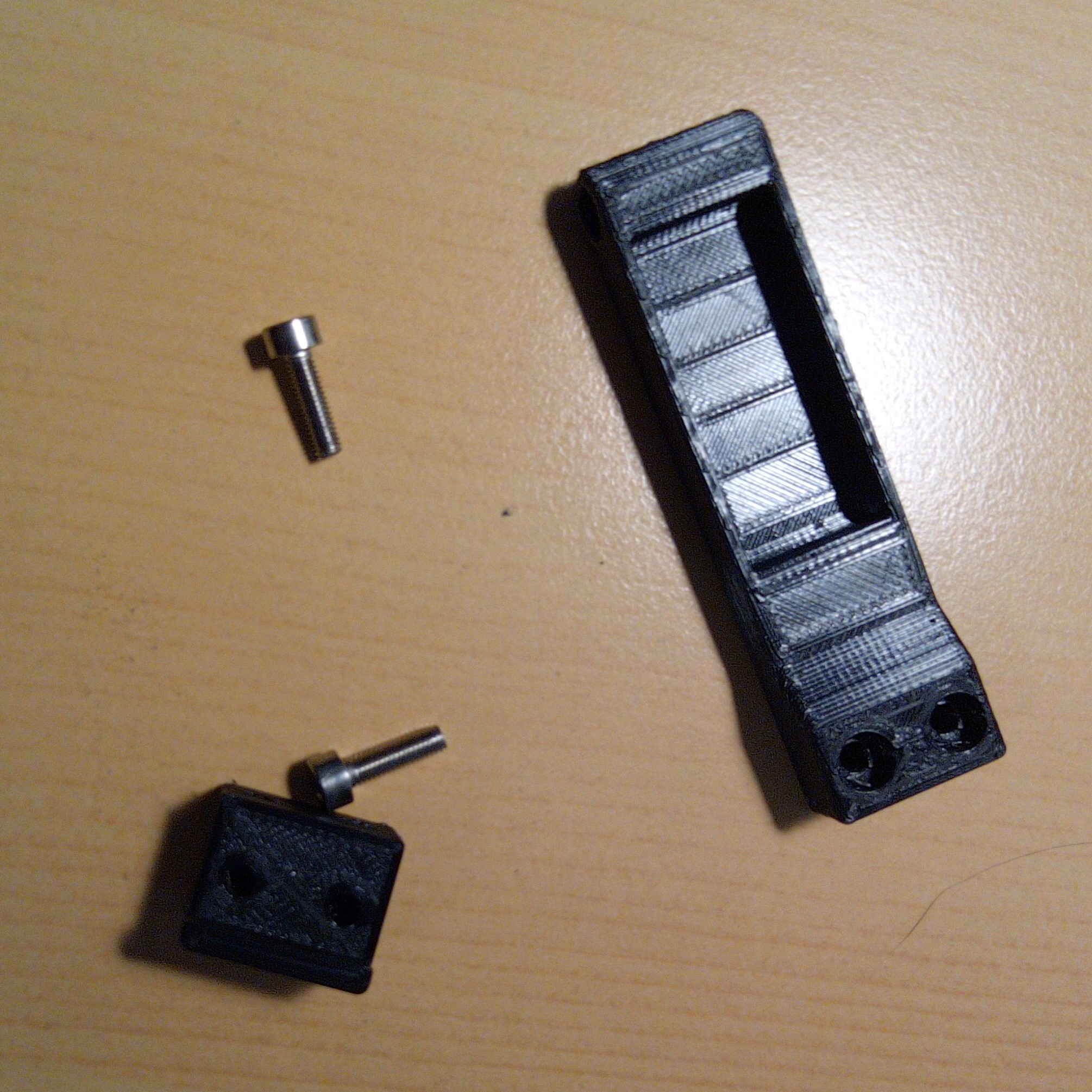
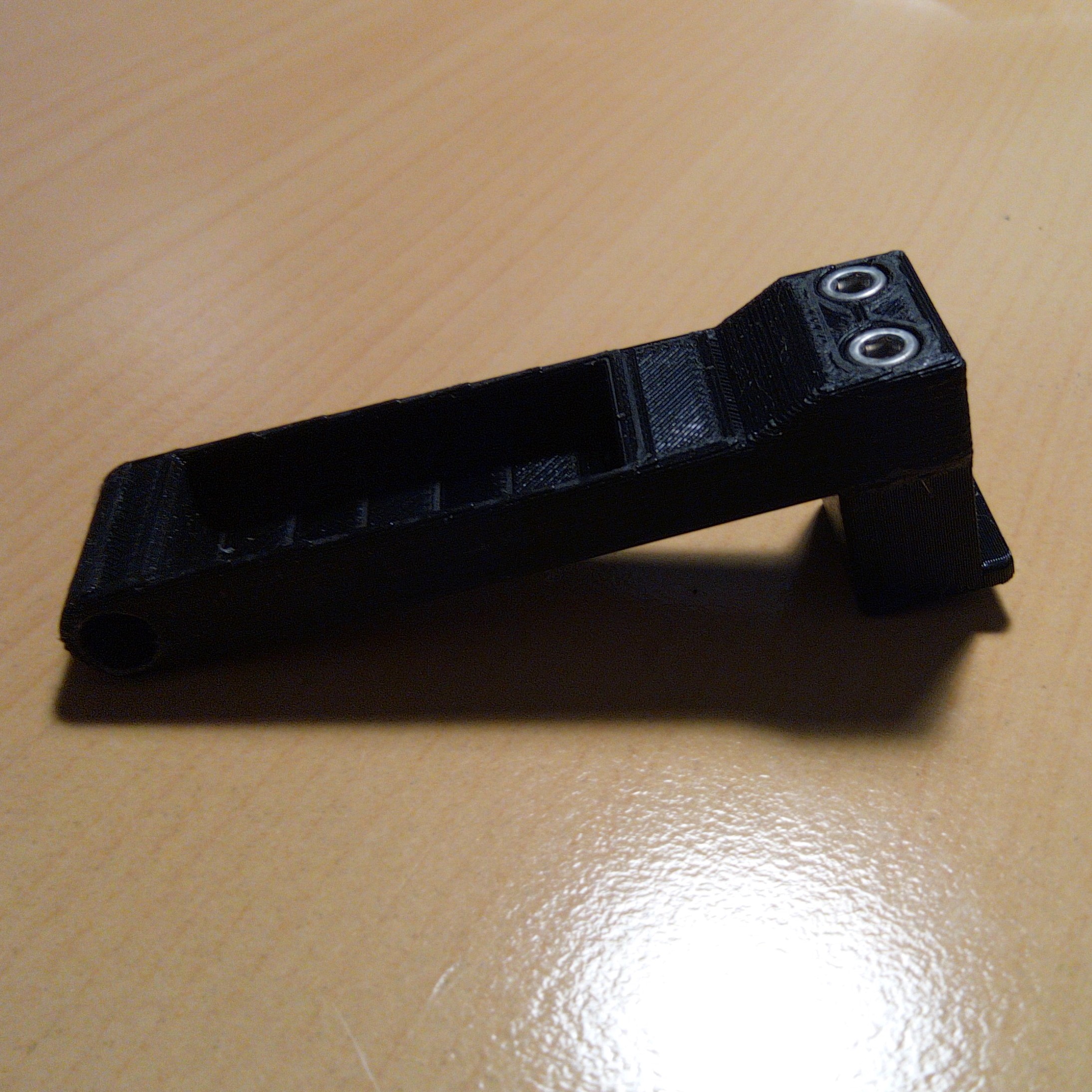
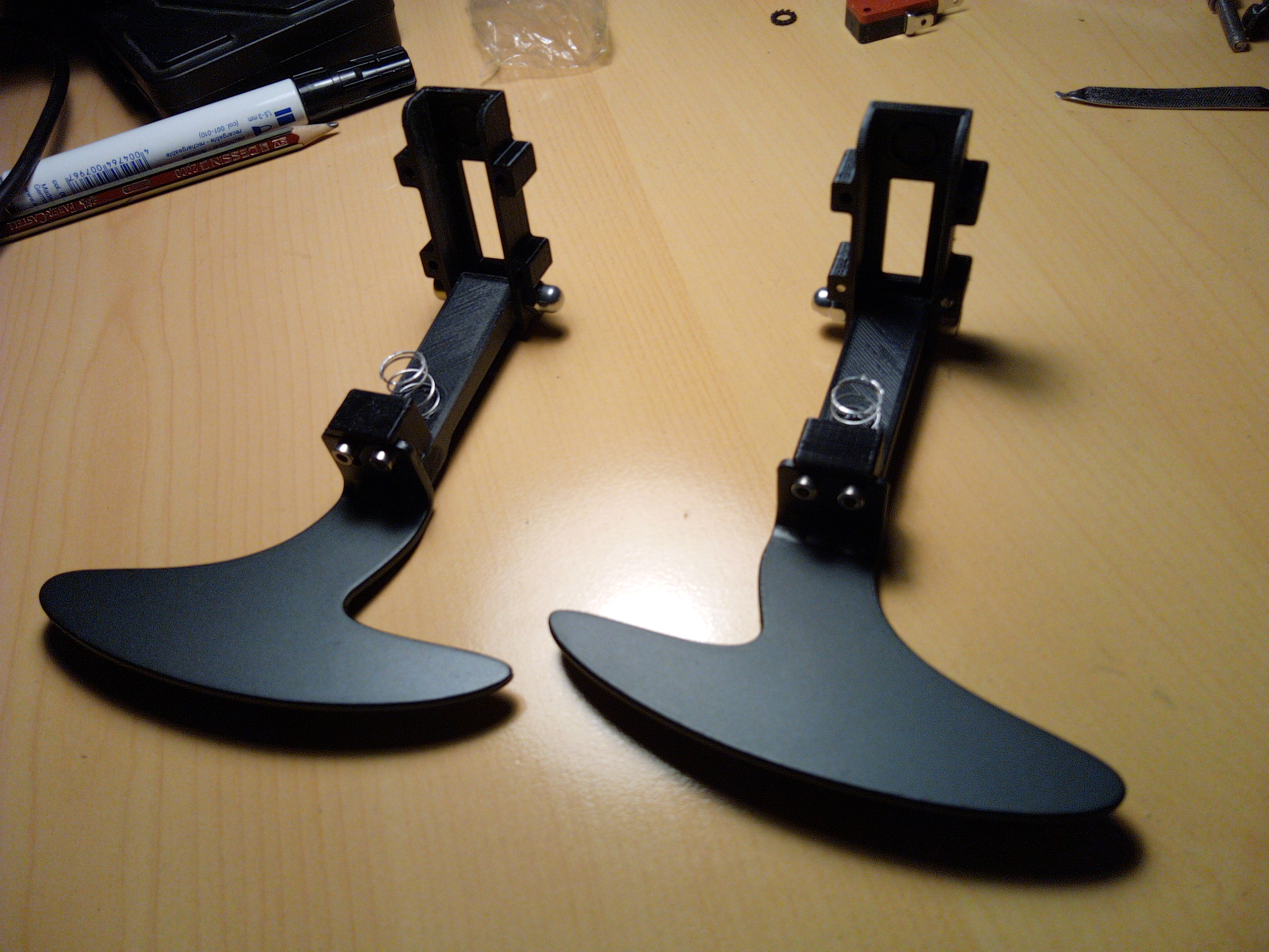
The single lever. Fits into the base plate, and uses a M4x22mm screw as axis. It screws the lever adapter, to fit the CSL BMW Motosport paddle shifters (it's my wheel). If you want, you can skip the lever adapter, and print a custom pladdle and fit directly into the lever. In the back, there's a small recession to fit the spring inside.
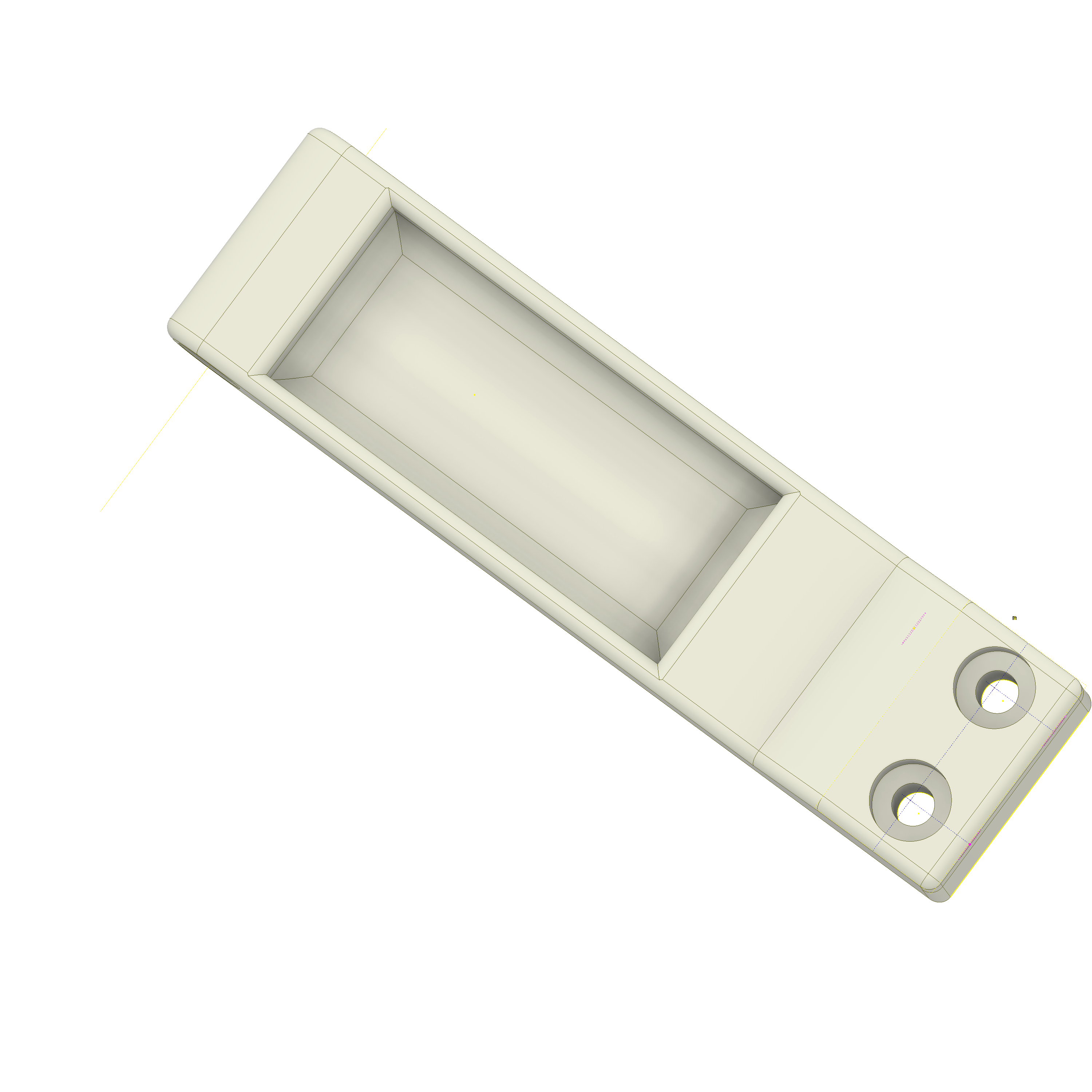
The lever adapter for the CSL BMW Motosport paddle shifters.
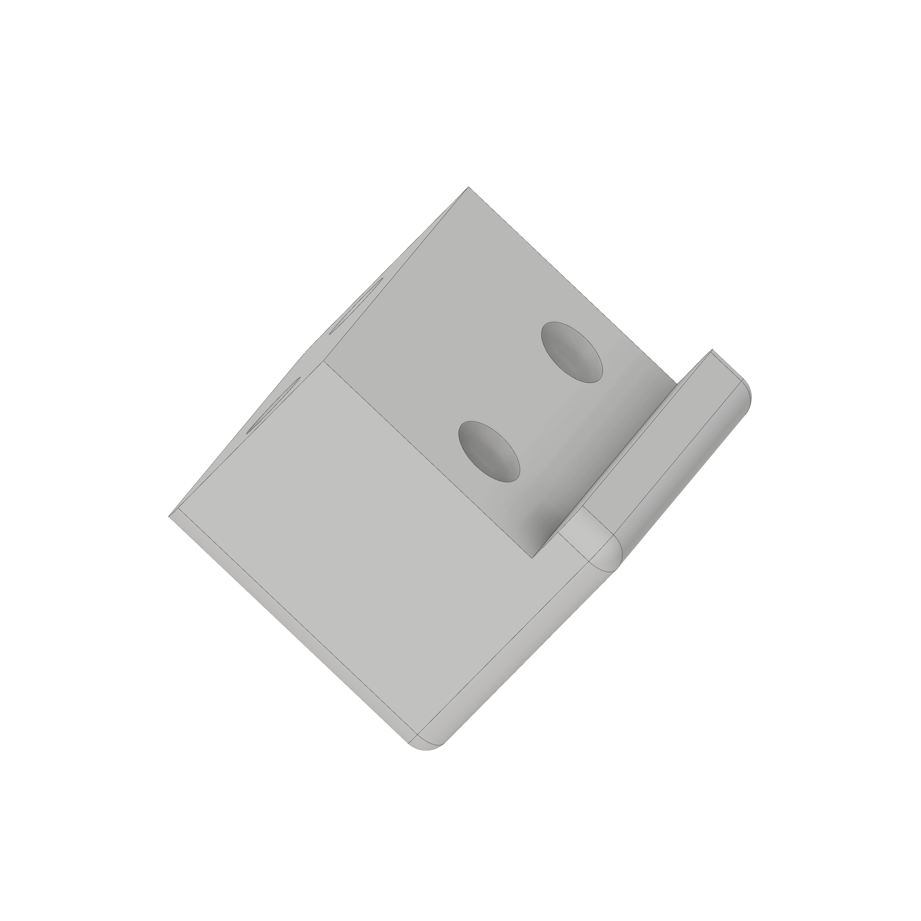
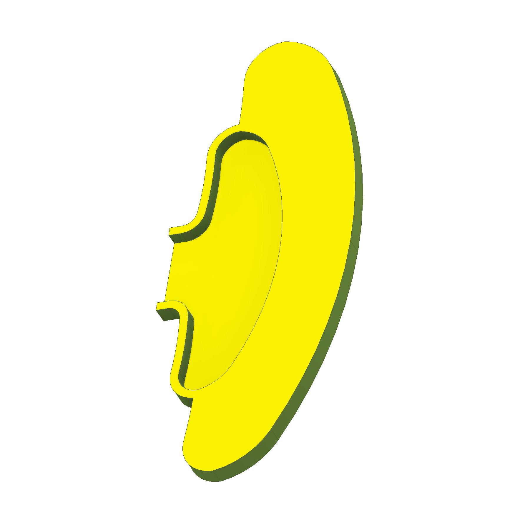
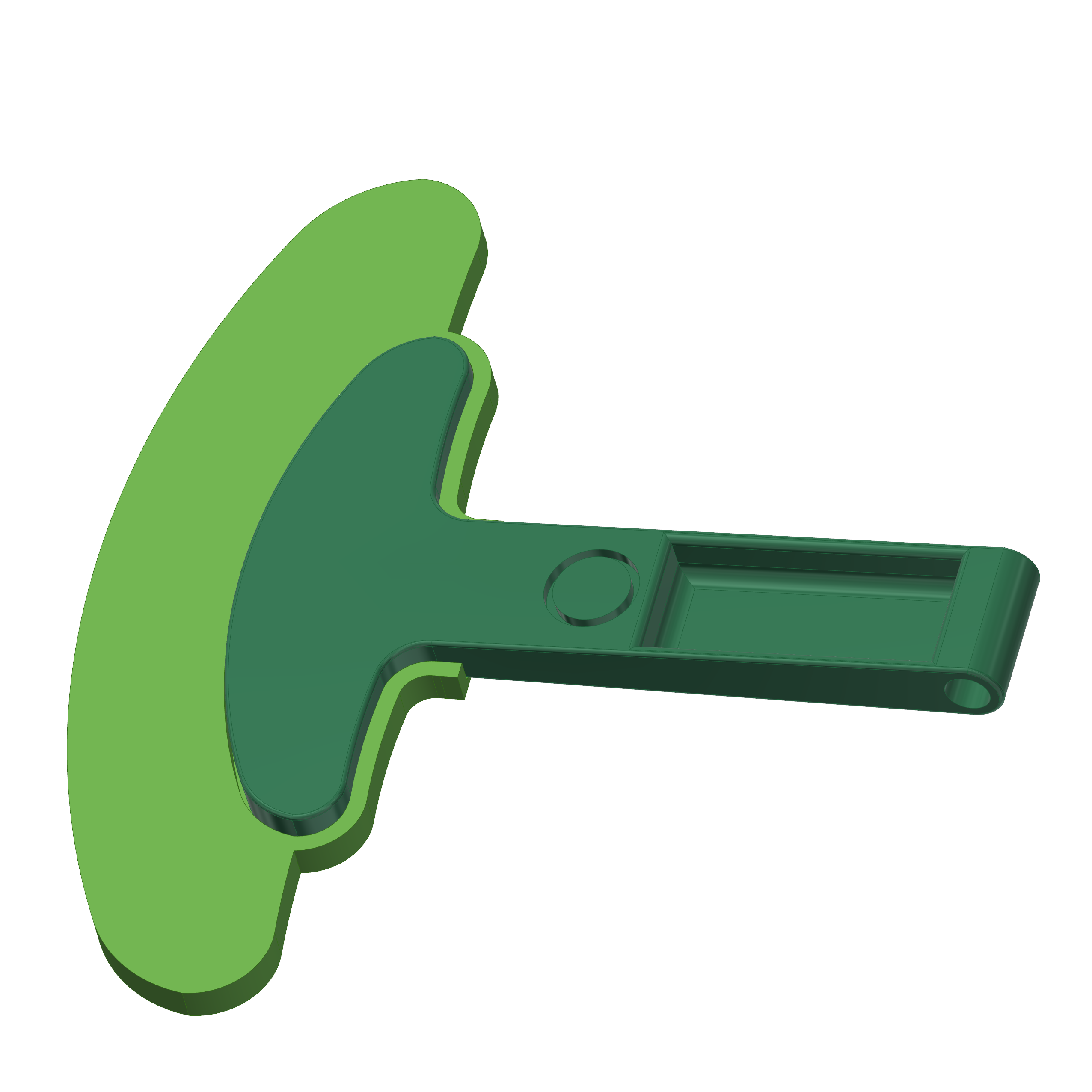
This lever has the paddle integrated, and it's a little longer
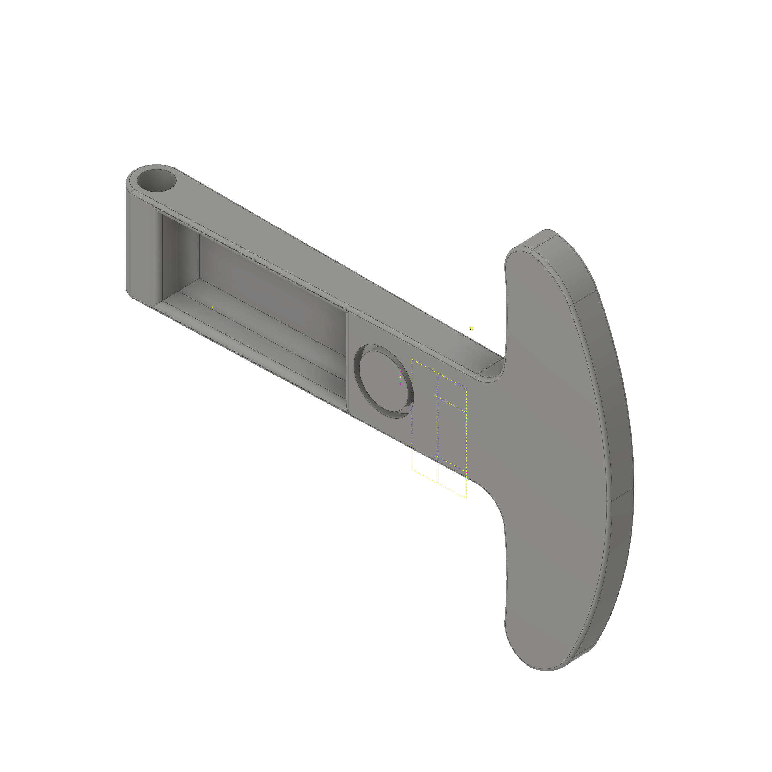
This add in increases the lever surface, doing the shifting easier. Just print, and glue with the alternate lever.
This part interfaces the plate with the lever using the base plate. This gives some angle and adds some separation to the base.

The lever is mounted here, and this is mounted on the cap to fit inside the plate.
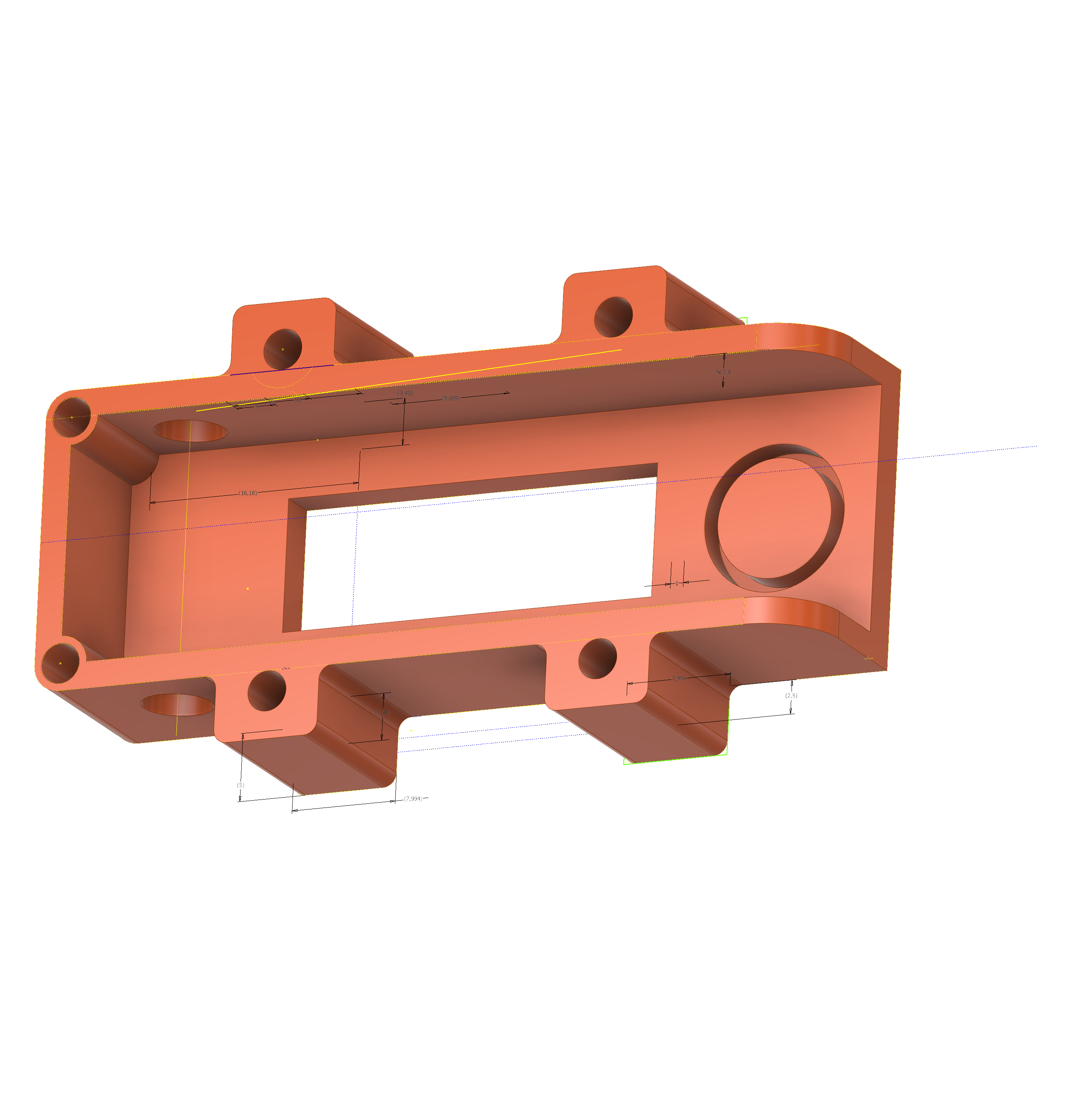
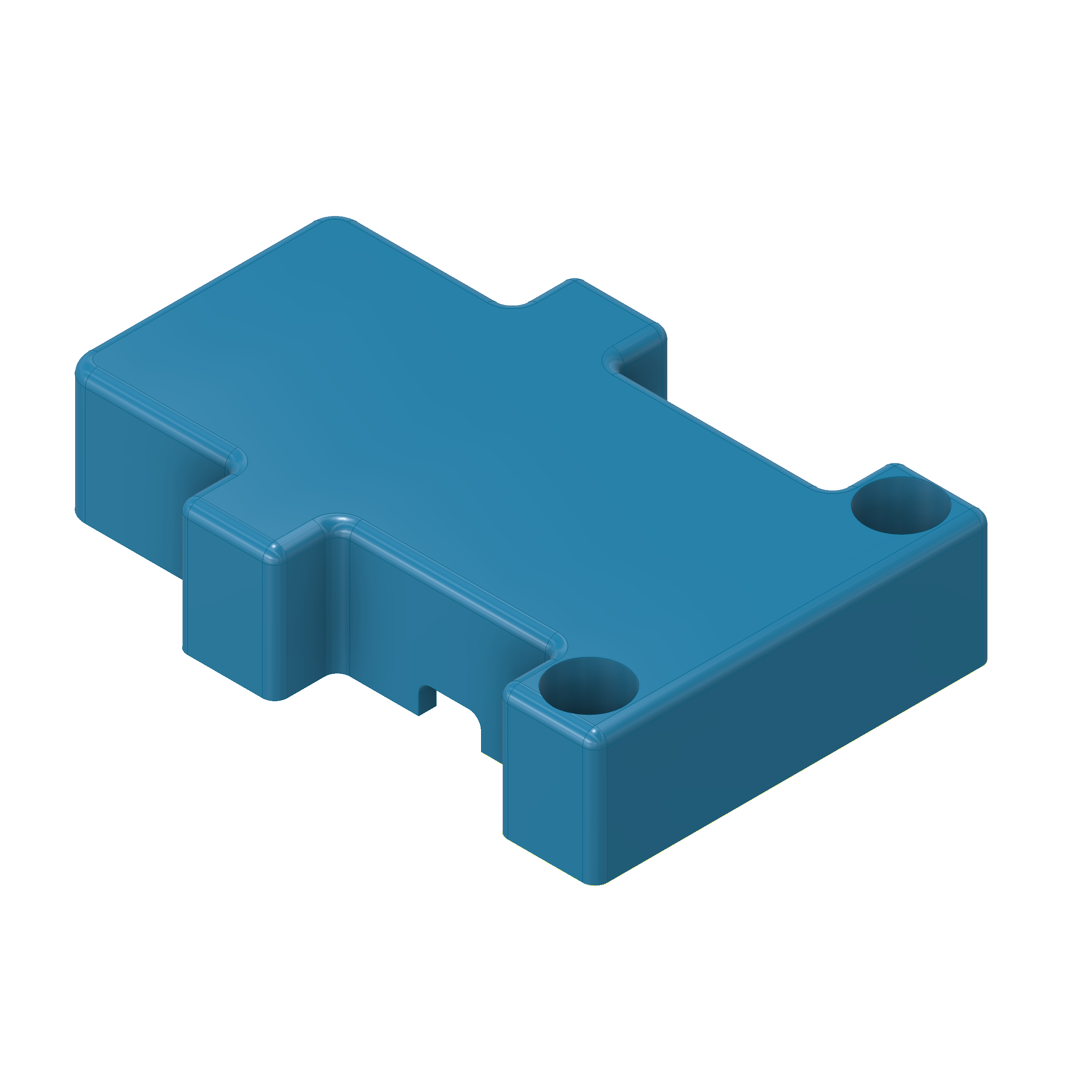
A simple cap for hidding the switches. If you use standard switches with the GT2, the rear cap collides with the wheel's screws. It's better using a low profile micro switch to save space and make a rear cap thinner (TODO)
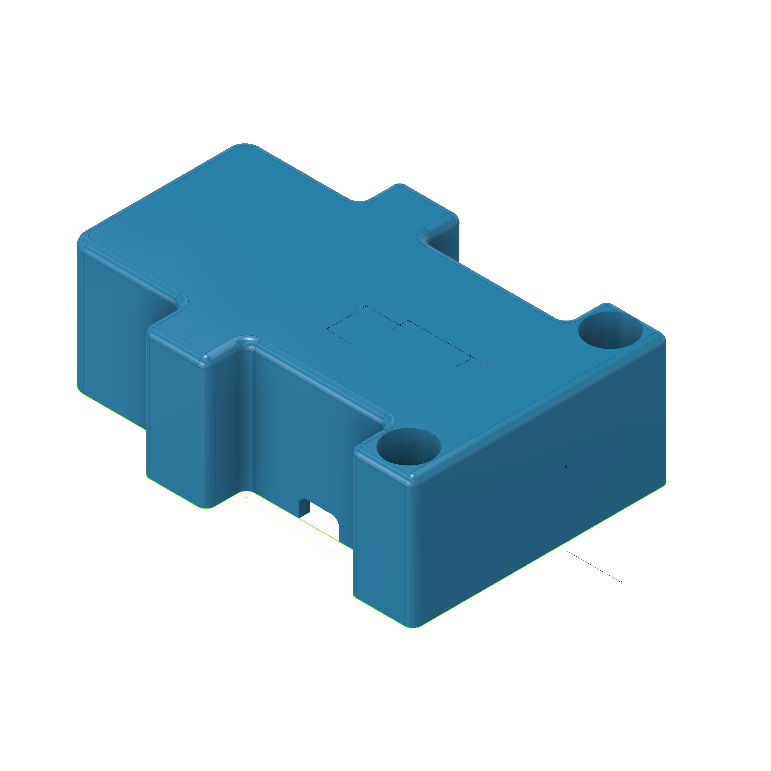
A simple cap for hidding the switches. If you use standard switches with the GT2, the rear cap collides with the wheel's screws. It's better using a low profile micro switch to save space and make a rear cap thinner (TODO). this cap is shorter and fits better with the BMW GT2 wheel.
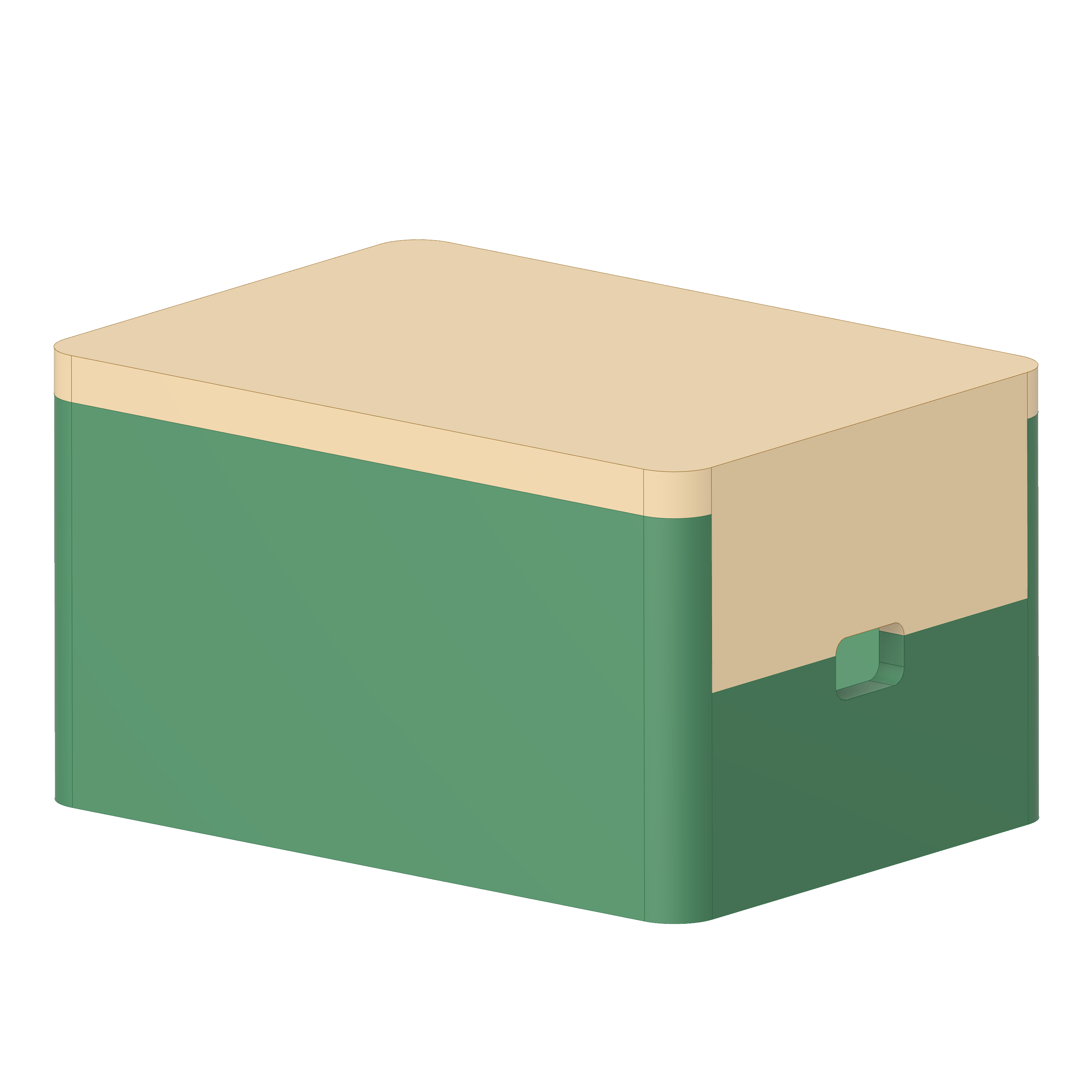
A simple box to hide the board and the cables.
See the following video to see how to mount the parts together.

First of all, mount the lever adapter into the levers. If you print your custom paddles, skip this step. Add the spring into the back, and glue it.
Insert the lever into the base plate, and pass the M4 screw as axis. Bolt it. Sand all the parts to get a smooth operation. Then, screw the cap tight. This part is the interface with the plate, and limits the travel of the lever. Screw the levers into the plate. You're done.
Put the plate in the wheel base, and place the reinforcements. Screw the big M6 screws in position, and tight it. I use some double tape to avoid any hold between reinforcement-cap and plate-wheelbase parts. Mount the wheel and check that nothings collides and the wheel moves freely and smooth. Now, we can mount the electronic components.
Fanatec wheel bases use a internal protocol to talk with their devices, and does this interface using RJ12-6p6c electrical interface cables. I don't wanna break my wheel base, so I check the internet, and find this amazing post: how to convert the Fanatec Shifter to USB Yin Zhong does some amanzing reverse engineering and, with the of this post and this document I start to manage how to implement the solution.
Pinout RJ12 (6P6C)
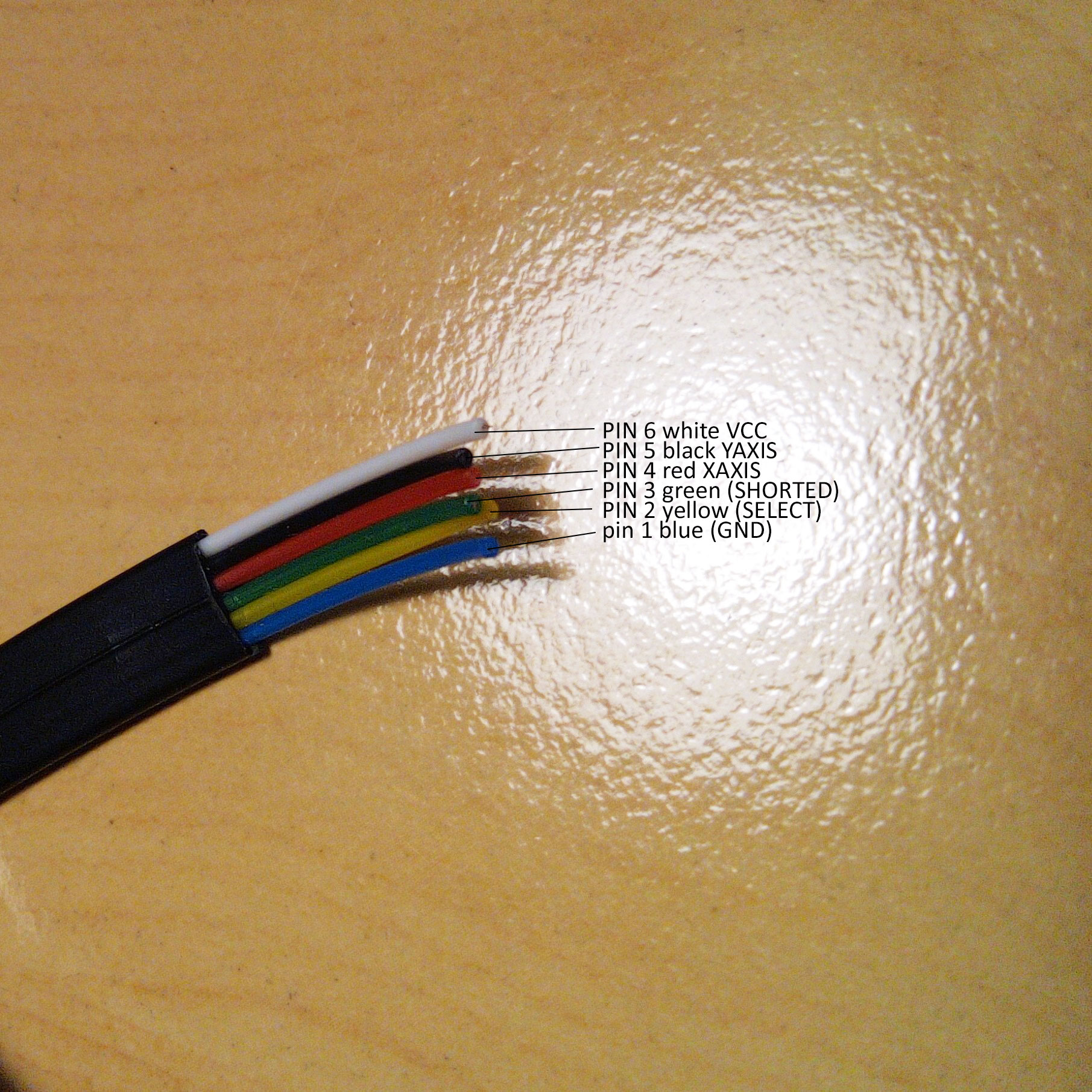
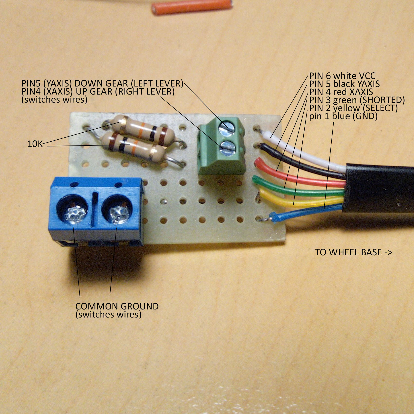
The official colors of the wire differs from mine, but the key is the cable is a RJ12 6P6C (6 poles, 6 connected). Pins are labeled using the following table (in CAPS are my wire's colors)
- GND
- SEQ low = H-pattern, high = sequential SEQ
- internally shorted to pin 2
- X axis (H-pattern); lever push (sequential)
- Y axis (H-pattern); lever pull (sequential)
- VCC
PIN numbering. The notch of the connector is in the bottom. PIN 1 starts in the right side of the connector.
RJ12 6P6C
+---------------------------------------------------------------+
|   6    |   5   |     4      |    3       |    2     |    1    |
| yellow | brown | red,orange | See below  | Not Used |  Black  |
|  WHITE | BLACK |     RED    |   GREEN    |  YELLOW  |   BLUE  |
|  VCC   | Yaxis |    XAxis   | Short pin 2|    SEQ   |   GND   |
+---------------------------------------------------------------+
                           |       |
                           | notch |
                           |       |
                           +-------+
- High means put it to VCC (high)
- Shorted is internally sorted (in our side), so connect PIN 3 with PIN 2.
- In our case, we want only SEQUENTIAL SHIFTER, so connect PIN 2 to HIGH (PIN 6). See the original post for info about H-shaped shifters.
- In SEQ (Sequential mode), PIN 5 (YAXIS) when LOW means "pull the lever" so downshift (lever of the left side of the wheel)
- In SEQ (Sequential mode), PIN 4 (XAXIS) when LOW means "push the lever" so upshift (lever of the right side of the wheel)
So the switches are mounted on a pullup configuration (using 10K resistors), so we can create a basic schema (sorry about my ASCII art):
SCHEMA

 (6) VCC
  x
  |
  |
  +---------[ 10K ]---+-------/ ----------+
  |                   | (4) X             |
  |                   x                   x (1) GND
  |                                       |
  +---------[ 10K ]---+------/ -----------+
  |                   | (5) Y
  |                   x
  |
  +------x (3)
  |
  +------x (2) SEQ
  |
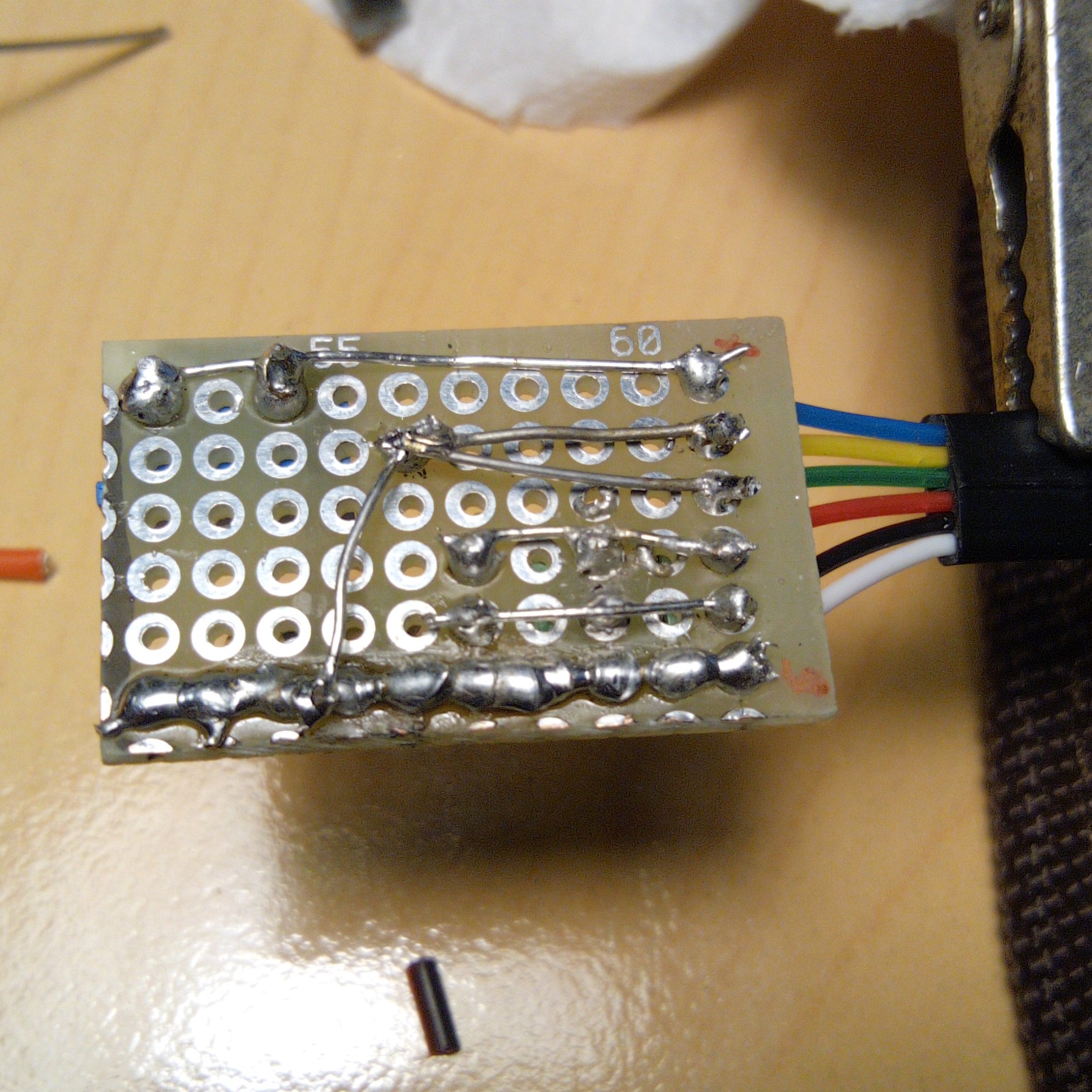
To implement it, I use some custom-made board (TODO: create a simple PCB). I add some connectors to fix the cables (to allow some mounting / unmounting) capabilities:
- Switches are normally open type.
- GND/COM is wired to GND (the big blue connector in the board)
- In the green connector, wire the NO (Normally open) wire of the switch.
- Connect the RJ12 to the SHIFTER2 port in CSL (I have a H-pattern connected to the SHIFTER1 port), start the wheel, and test with the Fanatec Device page that the switches works.
I protect the boards' soldered layer using hot glue. Then, I put it into the cablebox and ziptie it to the rig.
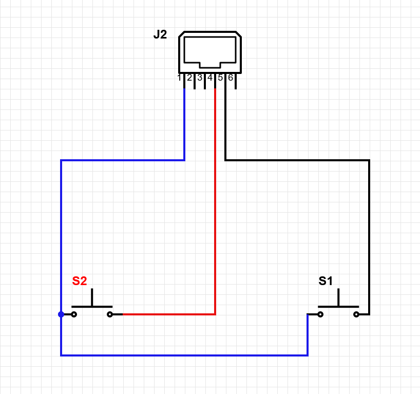
From RaceDepartment, user mechsicko suggest a simple wiring, tested and fully working.
Did a quick test before some racing tonight. The 3 wires on their own works for buttons. To test I just shorted the pull/push signal wires to ground (same thing a normally-open switch does) using Fanatec/windows > game controller to test. Behaves same as my Fanatec shifter in seq mode. The advantage of doing it the way you did is you could use yours in port 1 but for port 2 it's already done internally. The Vcc pin still had 3.3v but I didn't need > jump the other pins or bridge them to the Vcc.
tl:dr: simple 3 wire scheme is fine for shifter2 ^_^
You're done. Enjoy it.
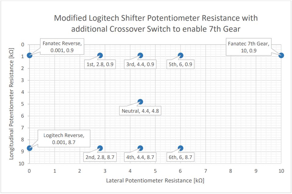
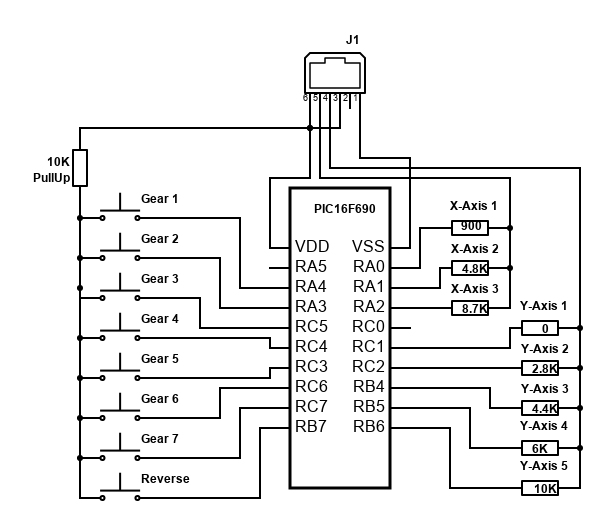
StuyoDGr8 has found a very clever solution to create an H-Shifter implmentation, and plug it directly to the fanatec base, as we can read in RaceDepartment Post. After some talking about tech details StuyoDgr8 comes with the following solution after reading this doc:
The idea is to use a PIC microcontroller (PIC16F690 in particular). It has low voltage requirements - can be powered with 2-5V, should be OK driven by the 3.3V on base. Code should be simple enough, in default it should keep mid-axis and Y resistors powered up and switch between X/Y combinations when button is activated. I put only one pullup resistor as we are using only one button at a time, should be fine.
I stay tuned on his advances !
Marek Towarek send me a comment with very valuable info about connecting pedals to a CSL base. You can read the comment here
The Universal* Shifter Interface for Fanatec Wheelbase is a DIY project aiming to interface custom shifters using the fanatec base, with lots of info. Check it out also.
