Arduino library for sending and receiving messages over the BMW infotainment bus (IBUS).
IBUS, or infotainment bus, is a BMW-specific controller network that enables infotainment and convenience systems to exchange data with each other.
Every time you interact with the vehicle, whether it be pressing a button on the steering wheel, opening a window or turning on the AC, data gets exchanged over the IBUS. In addition to that the IBUS is also used to exchange diagnostic messages and read fault codes.
The IBUS can be found on most BMW models produced between the late 90s and early 00s (most notably on the E46 3-series and E39 5-series).
Basic projects: interpreting steering wheel control commands, remote keyfob instructions and broadcast messages like road speed and engine RPM.
Intermediate projects: triggering stuff based on state changes (door/window has been opened/closed, wipers have been turned to level two, a key has been inserted into the ignition, left turn signal is on, etc.).
Advanced projects: manipulating inputs and outputs, for example: emulating a press of the "lock/unlock" button in order to automatically unlock the doors after the key has been removed (a feature that for some reason isn't available on the E46!).
This library can be found in the Arduino library manager. Simply search for IbusTrx and click install.
- Download this repository as a ZIP file
- Open the Arduino environment
- Go to Sketch -> Include Library -> Add .ZIP library...
- Install the ZIP file that you just downloaded
- Open the BasicReceive example to get a good understanding of how this library works
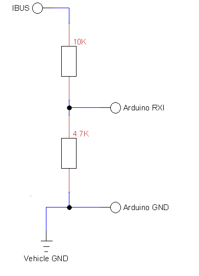
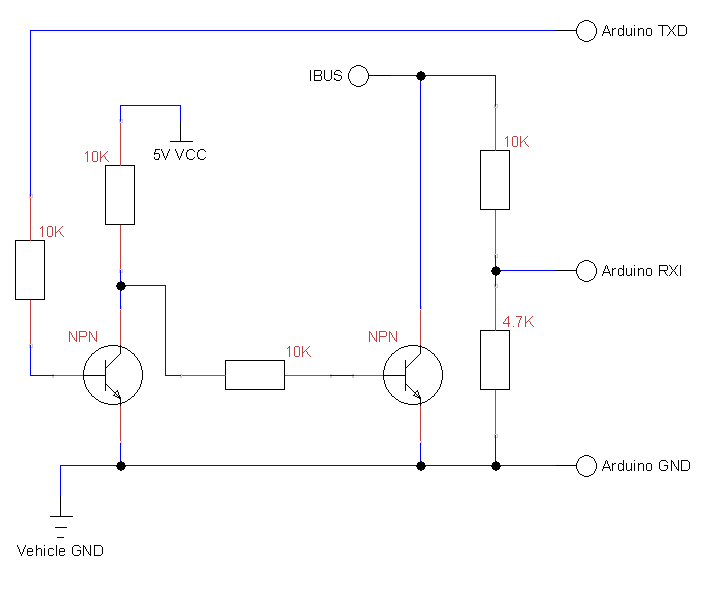
Warning: the IBUS operates at 12-15 volts, level shifting is required in order to make it work with the Arduino. Connecting the IBUS directly to your Arduino will let the magic smoke out.
Warning: the resistor values shown in these schematics are only suitable for Arduino boards that operate at a logic level of 5 volts.
Note: both schematics do not include any form of isolation or input protection. If you're worried about spikes on the IBUS causing damage to your Arduino you should definitely use an opto-isolater (or other form of isolation device).
This quick sketch shows you how to receive your first IBUS message, more elaborate examples are included with the library.
#include <IbusTrx.h>
IbusTrx ibusTrx; // create a new IbusTrx instance

void setup(){
  ibusTrx.begin(Serial); // begin listening on the first hardware serial port
}
void loop(){
  if (ibusTrx.available()) { // if there's a message waiting, do something with it
    IbusMessage message = ibusTrx.readMessage(); // grab the message
    unsigned int sourceID = message.source(); // read the source id
    unsigned int destinationID = message.destination(); // read the destination id
    unsigned int length = message.length(); // read the length of the payload
    unsigned int payloadFirstByte = message.b(0); // read the first byte of the payload
    // do something with this message
    if (sourceID == M_MFL) {
      // this message was sent by the steering wheel controls
    }
    if (destinationID == M_ALL) {
      // this is a broadcast message
    }
    // etc.
  }
}To make life easier, I defined the following IBUS addresses in this library:
| Name | Description |
|---|---|
| M_GM5 | body control module |
| M_DIA | diagnostic computer |
| M_EWS | immobilizer |
| M_MFL | steering wheel controls |
| M_IHKA | climate control panel |
| M_RAD | radio module |
| M_IKE | instrument cluster |
| M_ALL | broadcast message |
| M_TEL | telephone module |
| M_LCM | light control module |
The following diagnostic IO-addresses have been included for tinkering with the GM5 body control module:
| Name | Description |
|---|---|
| GM5_SET_IO | "set IO" diagnostic command |
| GM5_BTN_DOME_LIGHT | dome light button |
| GM5_BTN_CENTER_LOCK | center console lock/unlock button |
| GM5_BTN_TRUNK_OPEN | interior trunk unlock button |
| GM5_BTN_WINDOW_DRIVER_DOWN | driver window down button |
| GM5_BTN_WINDOW_DRIVER_UP | driver window up button |
| GM5_BTN_WINDOW_PASSENGER_DOWN | passenger window down button |
| GM5_BTN_WINDOW_PASSENGER_UP | passenger window up button |
| GM5_LED_ALARM_WARNING | red LED under interior mirror ("clown nose") |
| GM5_INPUT_STATE_DIGITAL | request digital IO states |
| GM5_INPUT_STATE_ANALOG | request analog IO states |
Warning: several safeguards are disabled when directly setting outputs, forcing a component to turn on may cause damage to mechanisms and/or electrical components. It's much safer to control inputs instead.
For example: telling the GM5 module that a window switch has been pressed is safer than directly sending power to the window motor.

