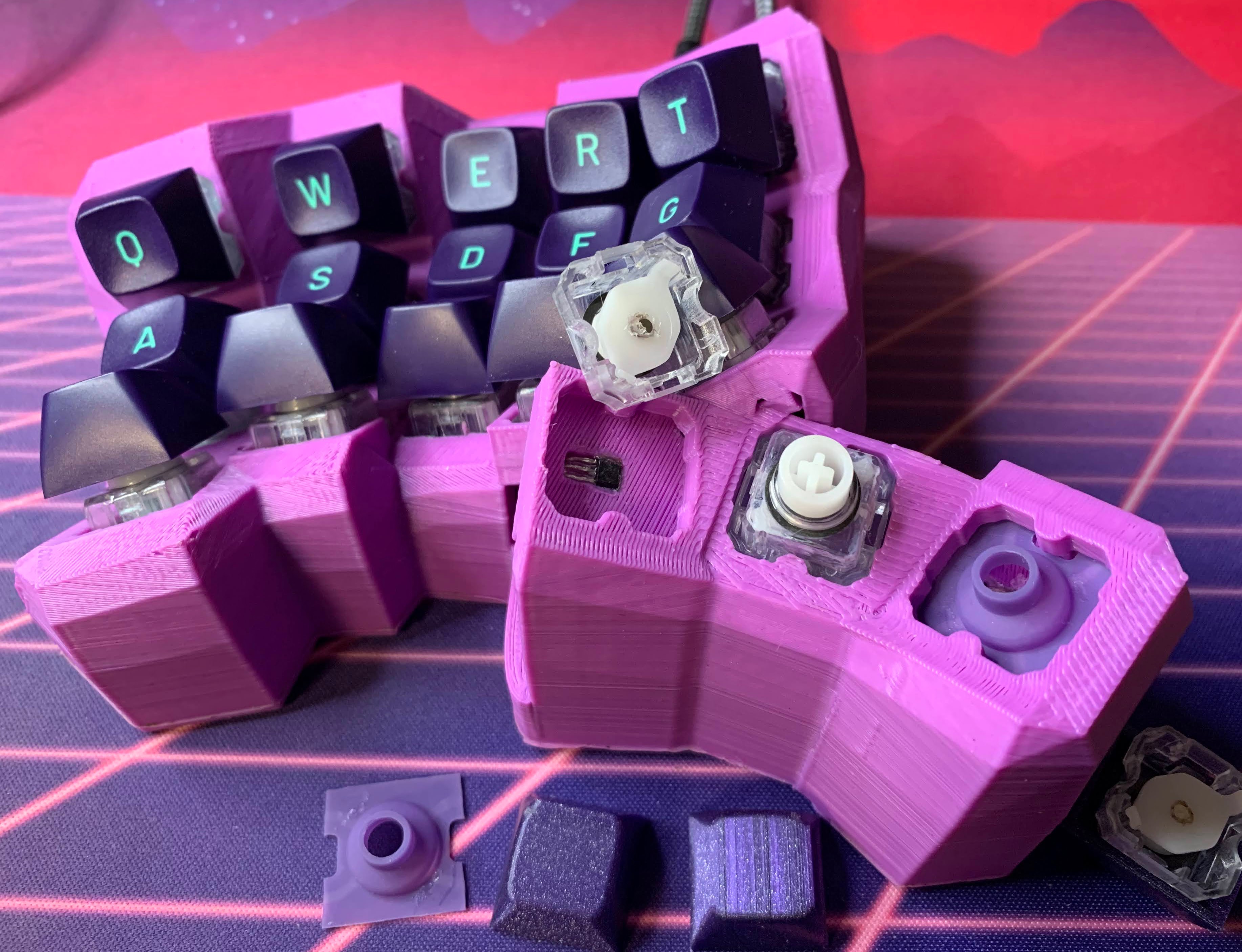
This is a library for generating paramaterized split-hand, concave, columnar, ergonomic keyboards in the spirit of the Dactyl, but written from the ground up in ocaml, rather than clojure. Dometyl also takes inspiration from a lineage of Dactyl-like keyboards that evolved from the original script, including the Compactyl itself a fork of forks of dactyl-manuform keyboards with many accumulated features, and the Skeletyl, a sleak, low-profile, open-case design built in Fusion360.
The name (rubber) dometyl comes from this library's introduction of a means of building split-hand concave keyboards with rubber domes. Taking advantage of the readily available Niz housing and sliders, and third-party non-sheet rubber domes (e.g. DES BKE DOMES), we can build dome-with-slider switches of our own without canabilizing an existing Topre or Niz board. You may be thinking that we still need expensive to obtain conical springs, and difficult to design (and very difficult to make use of inside a curved case) electro capacitive sensing PCBs to complete the picture, but then you would be wrong! One need simply glue magnets to sliders, and glue hall-effect sensors into a case, and voila the rubber dometyl is born.
The relevant code for generating the required keyhole can be found in the Niz module, the first example of a board configuration using them here, and the build showcase for it here.
Of course, if you aren't an insane person, the dometyl generator also supports more civilized Mx and Choc switch options.
This generator is written in ocaml, so you'll need to get an environment set up, including the package manager opam and the build system dune (which we'll install through opam). You'll of course also want OpenSCAD to preview/render/export the generated models.
After installing opam, you can run the setup.sh script for
convenience, or follow the instructions under the opam
dependencies sub-section, followed by copying
main.ml.example to dometyl/bin/main.ml.
All dependencies are available from the opam package manager including the build system dune, base and stdio (standard library replacements) from janestreet, and of course Scad_ml and ppx_deriving_scad for the modelling. I'd also recommend that you pick up the listed dev tools (which you'll want to get the corresponding packages/plugins for in your editor of choice).
Required:
- From inside dometyl:
opam install . --deps-only --with-doc
Highly recommended for dev experience:
opam install merlin ocp-indent ocaml-lsp-server ocamlformat ocamlformat-rpc
Online documentation is available here, and will be filling in over time.
- If you haven't already, copy main.ml.example
to
dometyl/bin/main.mland add a line for writing the scad of your generated model to the things directory. This can be done simply with the helper functionWrite.thingwhich can also optionally export and.stlusing the OpenSCAD cli. You can also pass your generatedCase.tto tent and bottom plate generation functions while you're there and write those to.scadas well. - Make a new
.mlfile in the boards library, maybe starting with a copy of and existing one and and modifying it to suit your preferences / fit your hand. - Generate scads/stls by running
dune exec dometylfrom the dometyl project folder. Files will be output to the things directory. Alteratively, if you have/installfswatch(cross-platform) orinotify(GNU/linux) on your system, you can usedune build -w @runto automatically build and execute on file changes. - Open generated
.scadfiles in OpenSCAD where they can be previewed/rendered/exported to.stl. If a viewed.scadis overwritten by compiling and running the generator, the changes will be visible in the GUI.
- An ugly recreation (yellow) of the
BastardKB Skeletyl (purple).
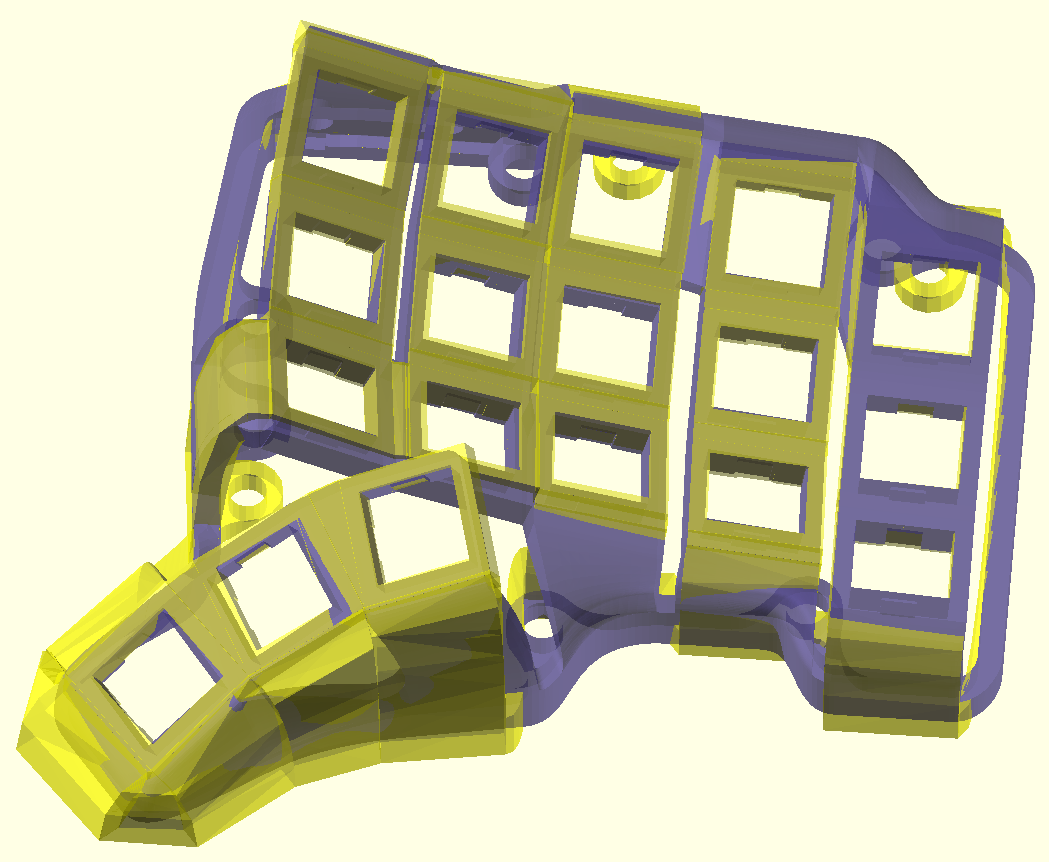 This configuration can be a good place to start if what you are looking for is
minor tweaks to the "standard" curvatures and offsets (or you want hotswap
sockets).
 - Configurable heat-set insert screw holes, magnet insets, or bumpon feet can be
placed at the base of walls of your choosing
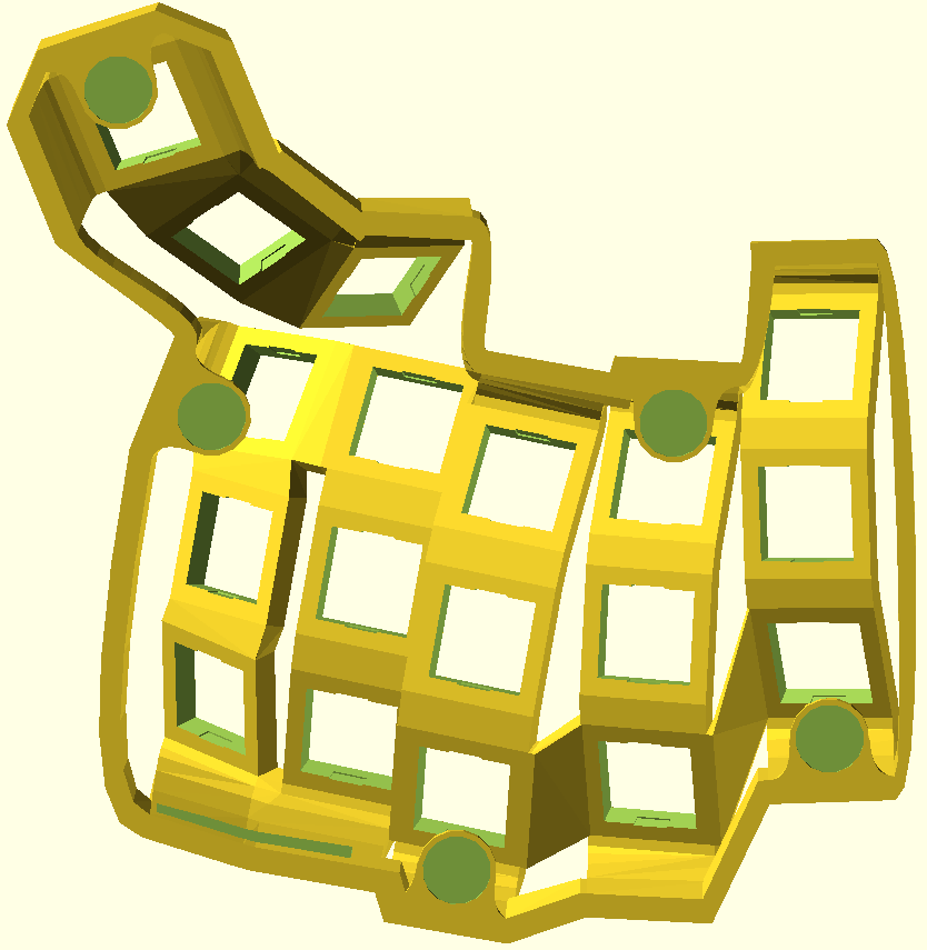
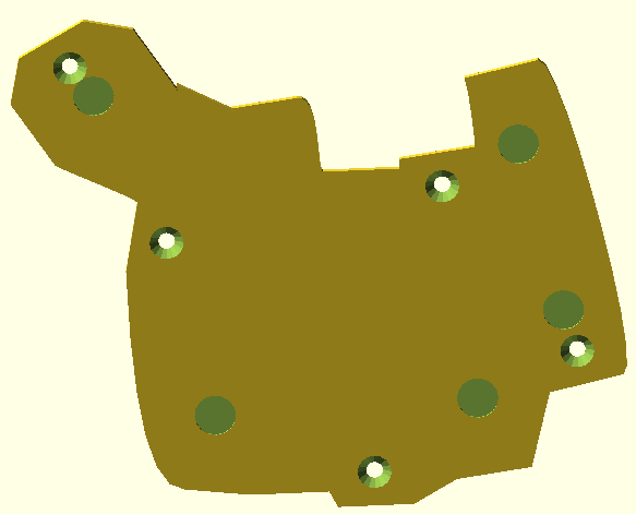
- Base plates and configurable tents can be generated to fit your case, using
either screws (into brass insets in the case), or magnets for mounting.
There is a showcase of finished builds and some example STLs here, including some pictures, bills of materials, and notes. If you've designed and built a board with the dometyl generator, and you are happy with it, please consider contributing the configuration to the boards library, and adding a folder to the boards showcase.
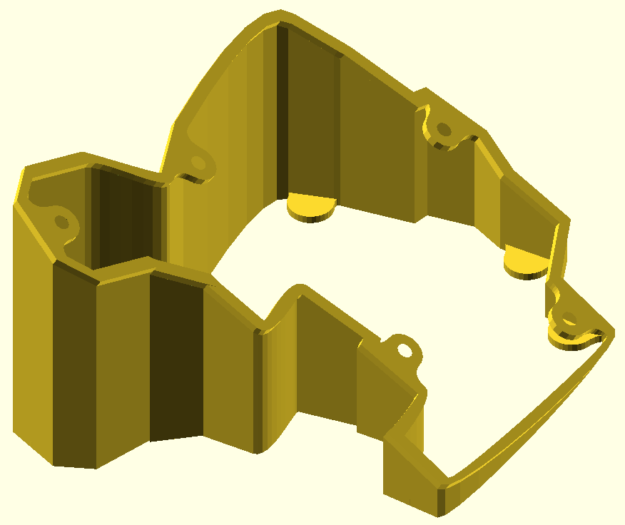
- A few solutions for MCU (elite-C and pro-micro currently) and TRRS jack
mounting are available at the moment. Rough placement is done with the help of
coordinates kept within the records of the
Case.ttype, with offset and rotation parameters available to fine-tune. - Firstly, there is support for using the familiar slot-in trays from
dereknheiley
(reversible, elite-C without and without reset button access) and
carbonfet (non-reversible,
elite-C and pro-micro). Eventually a more tailored tray holder that should be
available, but these existing stls can get the job done today.


- Second, the BastardKB shield
pcb used in the
Skeletyl (as well Quentin's other
boards) is supported as well. In addition to making the required insets/holes
in the case, the included helper functions will place configurable eyelets for
heatset inserts for mounting.
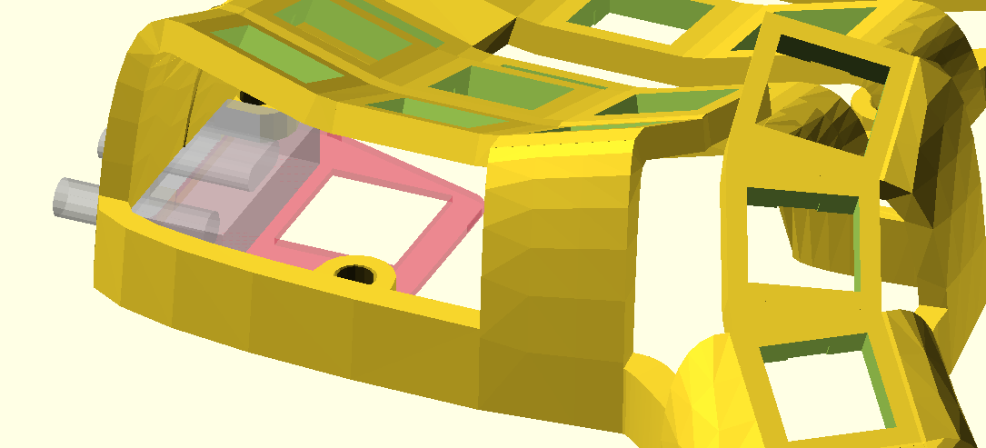
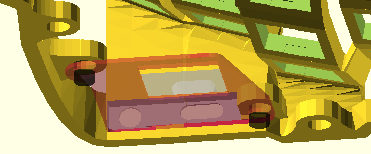 Some time ago, I ordered way too many of these off of JLCPCB, so if you are in
NA, something could likely be arranged! Alternatively, if would like to use
this mounting method rather than one of the trays, and you don't want get PCBs
made, there is an stl
available which you can print and solder your components around / glue to.
 - When using one of the trays, be mindful that the rails/slots are cut nicely in
the wall, and for an option that cuts ports into the wall, be sure that they
don't start too far away from the outside, so that the plugs will be able to
reach.
Walls.makehas anindex_thicknessparameter so that these holder-relevant walls can be tuned separately from the rest to adapt to your chosen mounting method.
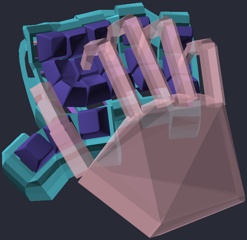 There is an as yet undocumented (and subject to evolution) Hand
module available to play around with. One can
generate hand from knuckle (base of proximal bones, or the meta-carpal for the
thumb) offset coordinates and bone lengths, then pose it with the available
flexion/extension/abduction/adduction/etc functions, and place it over the home
row of a generated
 Plate.t. Hopefully this can help give you a sense of what
column offsets and curvatures are going to work for you before you commit to a
test print.
Now and then, when you attempt to render a model, part of it will disappear. This is due to my imperfect abuse of OpenSCAD polyhedrons, which can fail to close when the points on each of their edges are at strange angles to eachother. The walls (from keyholes to the ground) and the connections between the walls both use polyhedrons so they are prone to breaking in this manner.
When this happens, and more than one piece of the case disappears (e.g. all of the connections between the walls), it can be useful to narrow down which part(s) in particular caused it, since it isn't necessarily all of them that have gone bad. To help with this, you can use Thrown Together mode in the OpenSCAD GUI (found in the View menu, or activated by hitting F12), which will show pink where you can see into the inside of any shapes (unclosed mesh).
Generally, you should be able to fix the problem by adjusting the parameters
used for drawing the polyhedrons in question. For walls, key values include
~d1 and ~d2, which specify how far they extend out from the side of the
plate, n_steps, which determines many points are used to draw the bezier
curves that form the edge of the drawn polyhedra, and n_facets, which sets how
many faces along the outer and inner sides of the wall there should be. If the
numbers of points are too high, or the curve of the wall is too tight, sometimes
the "bunching up" of points can make the faces difficult to close up. This can
ofter be remedied by increasing the number of facets, as the size of the
triangles generated by CGAL to close the mesh will be smaller / less stretched.
For the perimeter connections, you'll want to look at the various d and
scale parameters relevant to the one that has broken.
One day, some of these worries may be alleviated as I revisit/improve the solutions for polyhedron generation that are presently in use, for now, my apologies if they cause you any grief!
Contributions extending the functionality of the library (in addition to board
configurations as mentioned above) are welcome. If you plan to make a PR, please
have autoformatting working with your editor working (using the .ocamlformat
profile included in this repo) beforehand, and ammend/write doc comments in the
relevant interface files (I know my own coverage is still now 100% in that
respect, but I'll get there).
Copyright © 2021 Geoff deRosenroll
The source code for generating the models is distributed under the GNU AFFERO GENERAL PUBLIC LICENSE Version 3.
The generated models are distributed under the Creative Commons Attribution-ShareAlike 4.0 International (CC BY-SA 4.0).

