Series of extension tools for Asap.jl including:
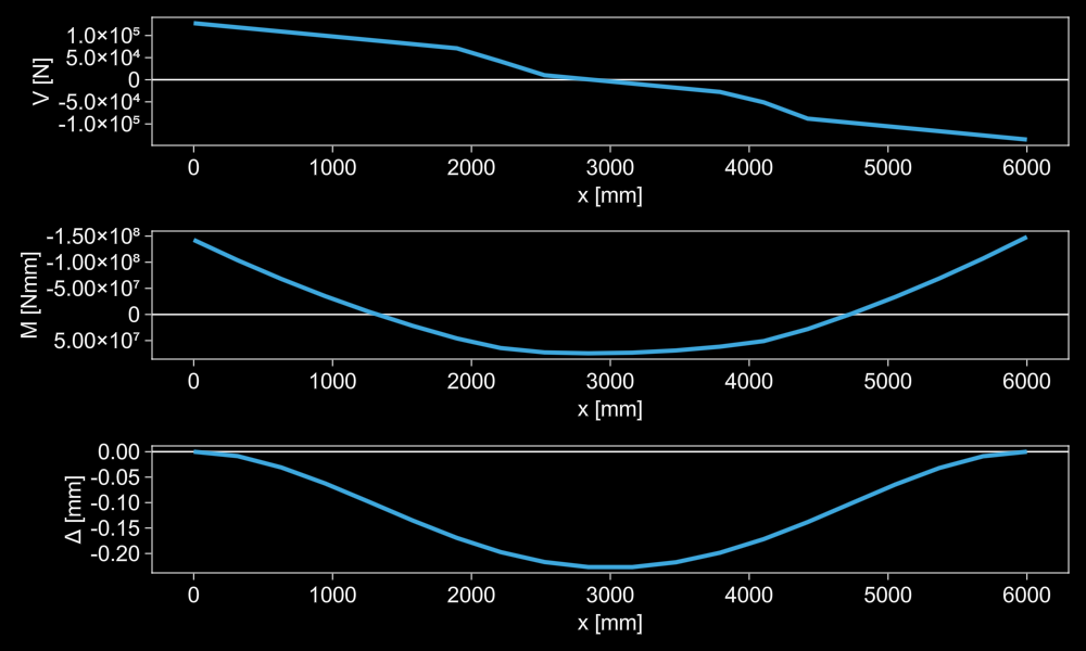
- Internal displacement analysis across an element:
ElementDisplacements - Internal force analysis across an element:
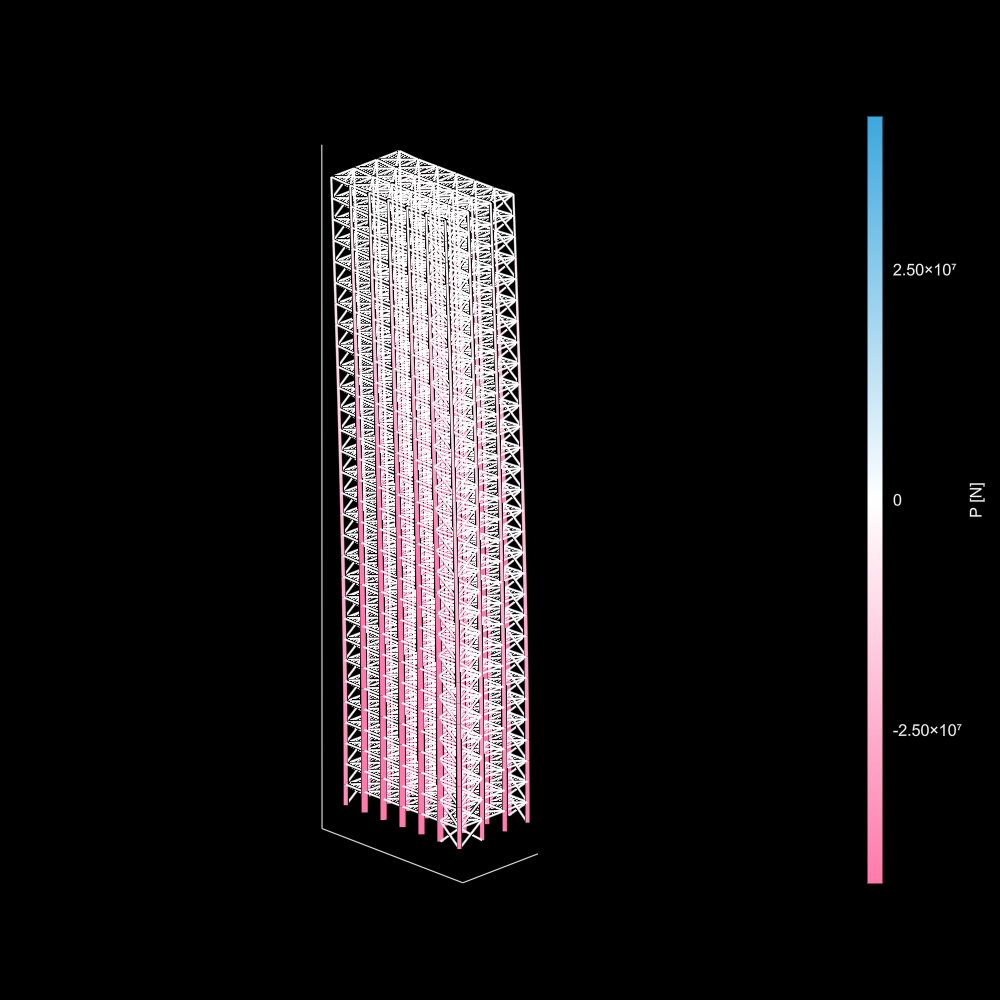
InternalForces,ForceEnvelopes - Automatic frame generation:
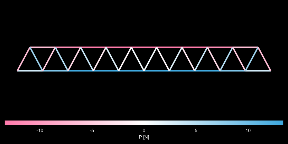
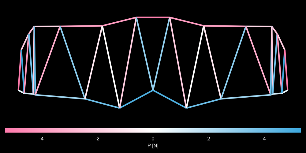
generateframe - Automatic 2D truss generation:
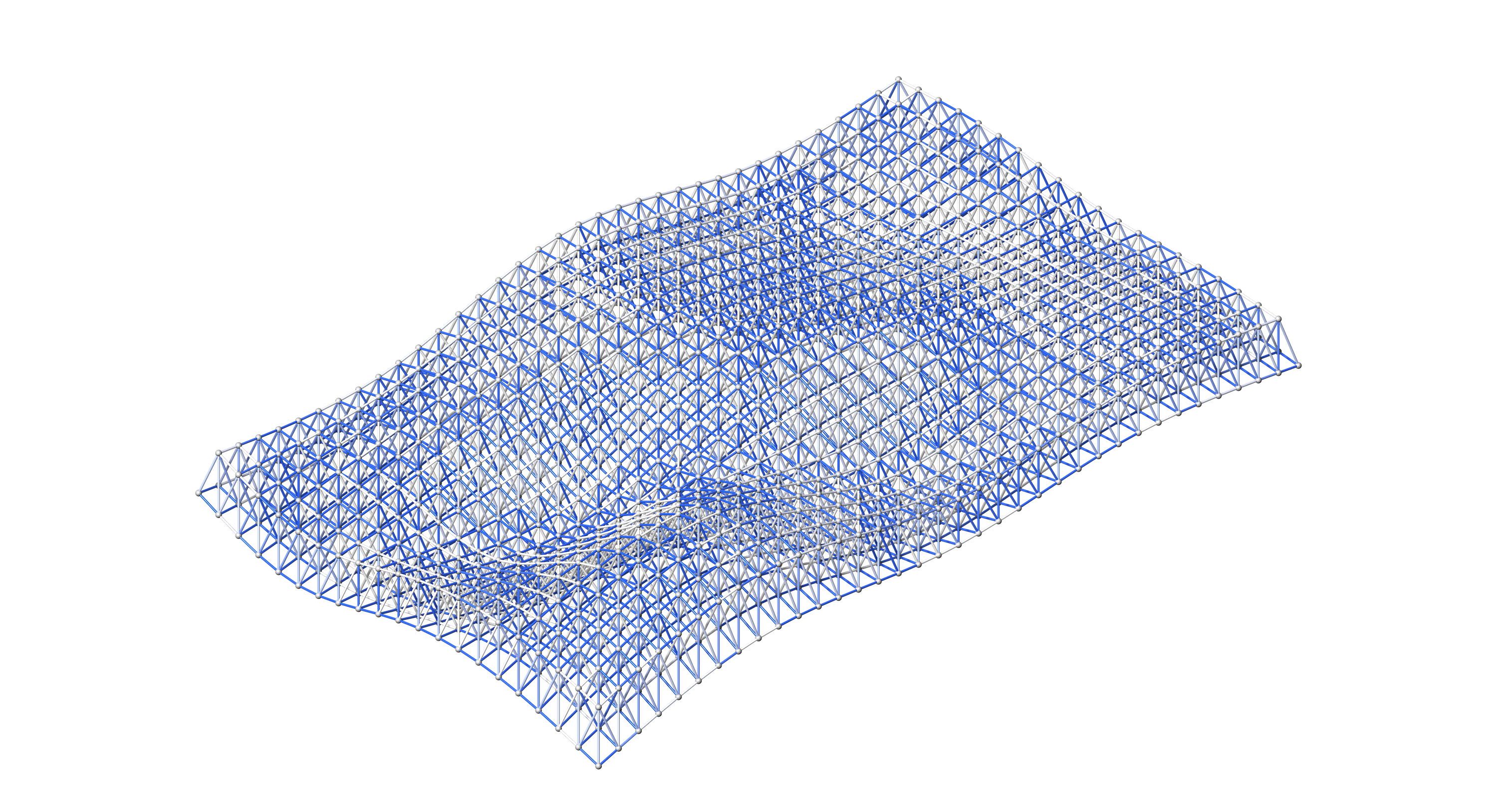
generatewarren2d - Automatic 3D spaceframe generation:
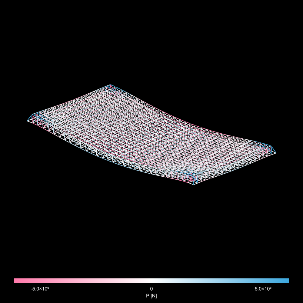
generatespaceframe
The internal forces for an element in an analyzed structure can be extracted via:
InternalForces(element::Element, model::Model; resolution = 20)Where resolution is the number of samples taken across the element. Results are stored in an InternalForces structure with the fields:
struct InternalForces
    element::Element
    resolution::Integer
    x::Vector{Float64}
    P::Vector{Float64}
    My::Vector{Float64}
    Vy::Vector{Float64}
    Mz::Vector{Float64}
    Vz::Vector{Float64}
end
Where y,z are with respect to the local coordinate system of the element.
Similar to force analysis, the transverse displacements can be extracted via ElementDisplacements(element::Element, model::Model; resolution = 20). Result is in the form:
struct ElementDisplacements
    element::Element
    resolution::Integer
    x::Vector{Float64}
    ulocal::Matrix{Float64}
    uglobal::Matrix{Float64}
    basepositions::Matrix{Float64}
end
Where ulocal and uglobal are
section = toASAPframe(rand(allW()), Steel_Nmm.E, Steel_Nmm.G)

n1 = Node([0., 0., 0.], :fixed)
n2 = Node([6000., 0., 0.], :fixed)
nodes = [n1, n2]

element = Element(n1, n2, section)
elements = [element]

load1 = LineLoad(element, [0., 0., -30])
pointloads = [PointLoad(element, rand(), 25e3 .* [0., 0., -rand()]) for _ = 1:5]
loads = [load1; pointloads]

model = Model(nodes, elements, loads)
solve!(model)

fanalysis = InternalForces(element, model)
danalysis = ElementDisplacements(element, model)
force/displacement analysis for all elements in a structural model can be generated via:
forces(model::Model, increment::Real)displacements(model::Mode, increment::Real)
Where increment is the absolute sampling distance along each element (not the number of samples taken in an element)
If the internal forces of an element across multiple load cases is desire, one can use:
load_envelopes(model::Model, loads::Vector{Vector}, increment::Real)This generates a vector of ForceEnvelopes for each element, which stores the lower/upper bounds of internal forces:
struct ForceEnvelopes
    element::Element
    resolution::Integer
    x::Vector{Float64}
    Plow::Vector{Float64}
    Phigh::Vector{Float64}
    Mylow::Vector{Float64}
    Myhigh::Vector{Float64}
    Vylow::Vector{Float64}
    Vyhigh::Vector{Float64}
    Mzlow::Vector{Float64}
    Mzhigh::Vector{Float64}
    Vzlow::Vector{Float64}
    Vzhigh::Vector{Float64}
endgenerateframe can be used to create and analyze a 3D frame structure with joist -> girder -> column hierarchy, bi-directional X-bracing and optional braces at each XY bay to simulate a diaphragm.
generateframe(nx::Integer,
    dx::Real,
    ny::Integer,
    dy::Real,
    nz::Integer,
    dz::Real,
    joistSpacing::Real,
    columnSection::Asap.Section,
    primarySection::Asap.Section,
    joistSection::Asap.Section,
    braceSection::Asap.Section)
Where:
nxnumber of bays in primary span directiondxbay spacingnynumber of bays in joist span directiondybay spacingnznumber of storiesdzfloor heightjoistSpacingspacing between joistscolumnSectioncross section properties for columnsprimarySectioncross section properties for primary beamsjoistSectioncross section properties for joistsbraceSectioncross section properties for braces
Optional inputs with default values:
diaphragm::Bool = falseadd a diaphragm to floor baysdiaphragmSection::Asap.section = nothingifdiaphragm == true, by default will assign the same section as the braces unless defined here.columnRelease::Symbol = :fixedfixedDOF releases for columnsprimaryRelease::Symbol = :fixedfixedDOF releases for primary beamsjoistRelease::Symbol = :joistDOF releases for joistsbraceRelease::Symbol = :freefreeDOF releases for bracescolumnPsi::Real = 0.Angle of roll Ψ for column LCSprimaryPsi::Real = pi/2Angle of roll Ψ for primary beam LCSjoistPsi::Real = pi/2Angle of roll Ψ for joist LCSbase::Vector{<:Real} = [0., 0., 0.]starting position of frame grid generation
The output is a Frame object that stores all user parameters as fields, and the analyzed structural model in Frame.model.
#choosing sections
begin
    W = allW()
    iStiffness = sortperm(getproperty.(W, :Ix))
    nsecs = length(W)

    mat = Steel_Nmm
    girder = toASAPframe((W[iStiffness])[Int(round(nsecs * 0.5))], mat.E, mat.G)
    joist = toASAPframe((W[iStiffness])[Int(round(nsecs * .2))], mat.E, mat.G)

    iArea = sortperm(getproperty.(W, :A))
    col = toASAPframe((W[iArea])[Int(round(nsecs * .75))], mat.E, mat.G)

    H = allHSSRound()
    iArea = sortperm(getproperty.(H, :A))
    nh = length(H)
    tube = toASAPframe((H[iArea])[Int(round(nh * 0.9))], mat.E, mat.G)

    girder.ρ = joist.ρ = tube.ρ = mat.ρ
end

# geometry hyperparameters for frame
begin
    nx = 3
    ny = 6
    nz = 30
    dx = 6000
    dy = 5000
    dz = 4200
end

# generate and extract
frame = generateframe(nx,
    dx,
    ny,
    dy,
    nz,
    dz,
    500,
    col,
    girder,
    joist,
    tube;
    columnPsi = pi/2,
    diaphragm = true,
    );

model = frame.model;generatewarren2d(n::Integer,
dx::Real,
dy::Real,
section::Asap.AbstractSection;
type = :arch,
base = [0., 0., 0.])Where:
nnumber of bays (must be odd)dxbay spacing in X directiondydepth of trusssectionelement section
With optional parameters:
type::Symbol = :arch: can be:archor:catenarywhich chooses with the longer chord is the tensile or compressive chordbase::Vector{<:Real} = [0,0,0]: base point for truss generation
#parameters
n = 11
dx = 1500
dy = 1400
section = toASAPtruss(rand(allHSSRound()), Steel_Nmm.E)

#generate
warrentruss = generatewarren2d(n,
    dx,
    dy,
    section)

#extract
truss = warrentruss.modelgeneratewarren2d(xpositions::Vector{<:Real},
ypositions::Vector{<:Real},
ypositions2::Vector{<:Real},
section::Asap.AbstractSection;
type = :arch,
base = [0., 0., 0.])Where:
xpositionsx-positions of long chord nodes (should generally be in increasing order)ypositionsy-positions of long chord nodes.length(xpositions) == length(ypositions).ypositions2y-positions of short chord nodes. The x-positions are always centered between two long chord nodes.length(ypositions) == length(ypositions2) + 1
#irregular
xpos = cumsum(rand(7) .* 2000) .+ 500
ypos = - sort(rand(7) .* 1000); ypos[1] = ypos[end] = 0.
ypos2 = sort(rand(6) .* 1500) .+ 1500

truss = generatewarren2d(xpos,
    ypos,
    ypos2,
section)generatespaceframe(nx::Integer,
dx::Real,
ny::Integer,
dy::Real,
dz::Real,
section::Asap.AbstractSection;
support = :corner,
load = [0., 0., -10.],
base = [0., 0., 0.])Where:
nxnumber of bays in x-directiondxbay spacingnynumber of bays in y-directiondybay spacingdzspaceframe depthsectionelement properties
With optional parameters:
support::Symbol = :cornersupport condition types. Choose from::cornersupport all nodes in each corner bay of the spaceframe (16 nodes total):xsupport all the extremity nodes aligned with x-axis (1-way span):ysupport all extremity nodes aligned with y-axis (1-way span):xysupport all perimeter nodes (2-way span):centersupport the nodes that form the center bay of the structure
load::Vector{<:Real} = [0, 0, -10]load applied to all bottom nodes (excluding supports)base::Vector{<:Real} = [0,0,0]starting point for generation
nx = 20
dx = 1000.
ny = 31
dy = 1300.
dz = 1250.

sec = rand(allHSSRound())
tube = toASAPtruss(sec, Steel_Nmm.E)
σ = 350.

sf = generatespaceframe(nx, dx, ny, dy, dz, tube; load = [0., 0., -30e3]);

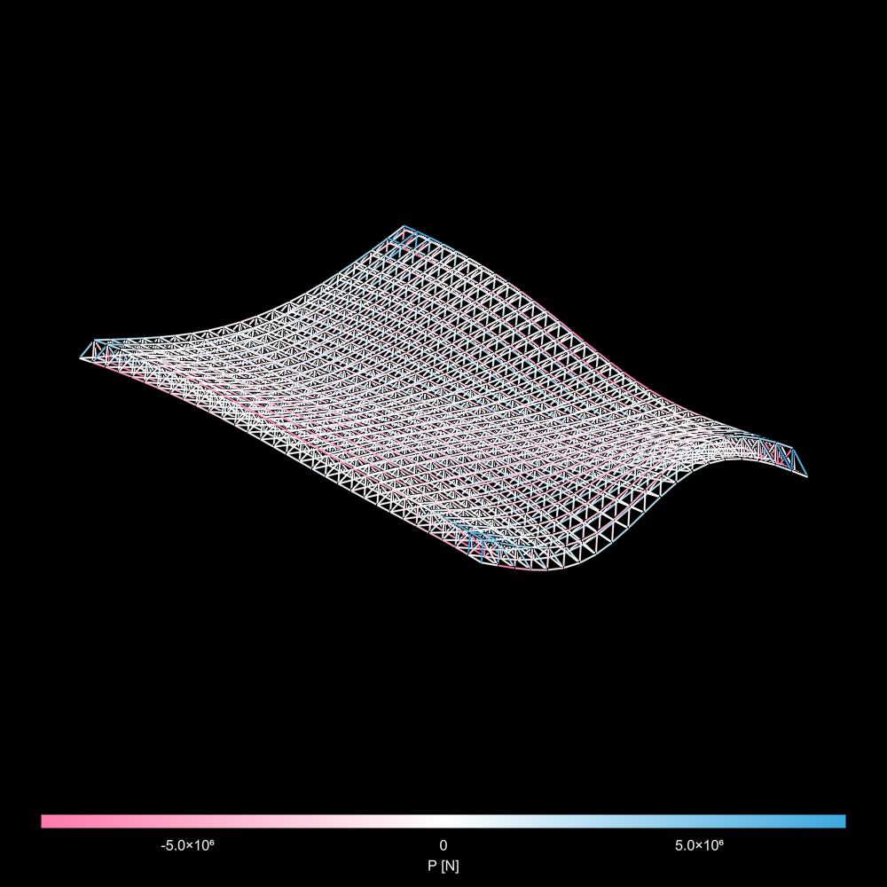
truss = sf.truss;generatespaceframe(nx::Integer,
dx::Real,
ny::Integer,
dy::Real,
z0::Real,
interpolator::Interpolations.AbstractExtrapolation,
section::Asap.AbstractSection,
offset = false;
support = :corner,
load = [0., 0., -10.],
base = [0., 0., 0.])The major differences are:
dzis replaced withz0, the initial offset between the top surface and bottom surface of the spaceframeinterpolatordefines the z-height function of the spaceframe nodesoffsetdetermines whether the bottom plane remains in place or follows the top plane
interpolator must define a function that takes in two inputs (x,y coordinates) and returns a scalar value (z coordinate):
Where: $$ x \in [0,1]\ y \in [0,1] $$
This can be generated using the cubic_spline_interpolation function in Interpolations.jl. See example below:
n = 4
x = range(0,1,n)
y = range(0,1,n)
z = rand(n,n) .* 4500

itp = cubic_spline_interpolation((x,y), z)

@time sf = generatespaceframe(nx, dx, ny, dy, dz, itp, tube, true; load = [0., 0., -30e3]);
truss = sf.truss;