LEDs not working
ecraven opened this issue · 21 comments
I've soldered the resistors and LEDs in as follows, caps-lock does light the led in a second attached keyboard, but not in the one I built:
The SMD LEDs have a small bar on the back, I oriented that in the same direction as the bar of the diode symbol is on the silkscreen.
Is there a way to light up all the LEDs, for testing? How would I best debug this?
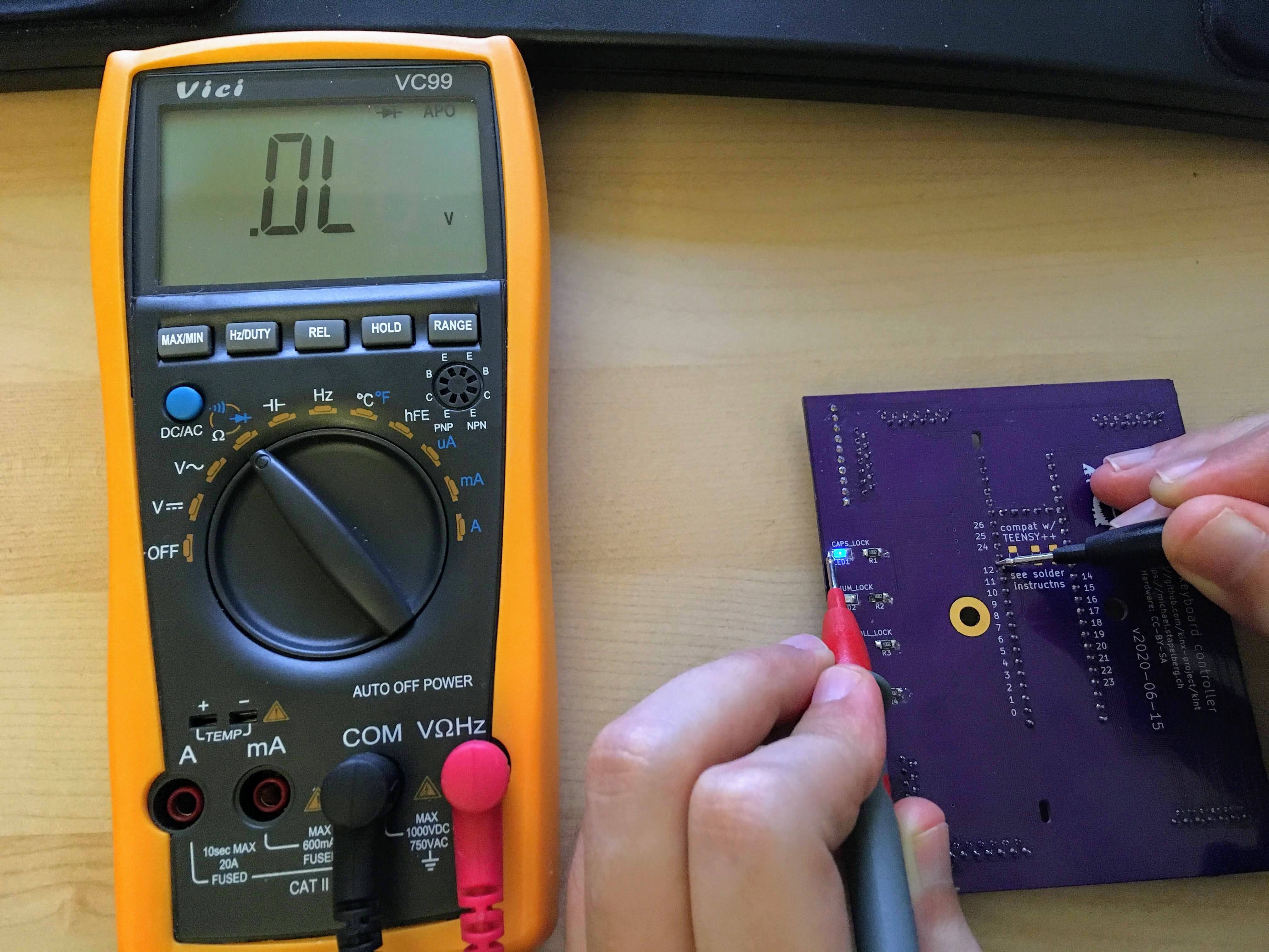
The LED tester on my multimeter lights them all up, with the Black probe connected to A and the Red to C. Is that the correct direction?
I tried changing direction of the caps-lock led (wow, smd unsoldering is much less fun than soldering), no luck :-/ any way to just toggle the leds with keys?
I can expand on this tomorrow (it’s getting late), but https://github.com/kinx-project/qmk_firmware/blob/kint36/keyboards/kinesis/kint36/kint36.c is the file that handles the LEDs.
Maybe you can play around with that to learn something new. E.g., comment out led_set_kb() and set individual LEDs in led_init_ports().
Does the Teensy 3.6 power LED light up?
Yes, the power led lights up fine. I'll try tomorrow to just turn all leds on on startup. Thanks for the hint!
Edit: Tried right away, I replaced all LedTurnOff with LedTurnOn, still not a single LED on. the led tester on my multimeter lights up all LEDs (though they are right now soldered in different directions, so at least some of them should work).
Just tested it on my kint36: the LEDs work fine here.
When flashing the Teensy (i.e. after pressing the button), all LEDs turn on briefly for me.
Can you share whether you ordered the components (specifically LEDs and resistors) exactly as referenced on the kint page, or whether you made any adjustments?
The LED tester on my multimeter lights them all up, with the Black probe connected to A and the Red to C. Is that the correct direction?
The black probe (COM) should be connected to the C (cathode) end.
For me, the LED doesn’t light up if I swap the probes around.
This doesn’t sound right to me, so maybe the mark is the wrong way around after all? Or your probes are swapped around?
Regarding expected multimeter measurements:
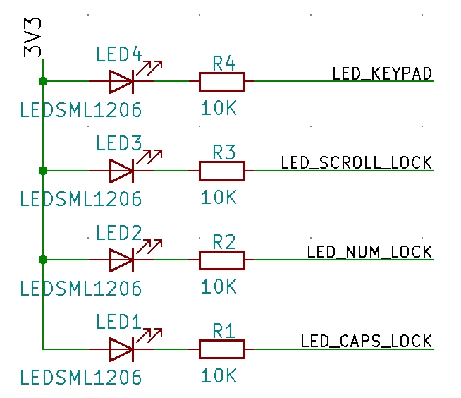
On the LED Anode (A), you should be measuring 3.3V always.
On the LED_* pins (12, 24, 25, 26, see https://github.com/kinx-project/kint/blob/master/schematic-v2020-06-30.pdf), you should be measuring 3.3V when the LED is turned off, and 0V when the LED is turned on.
wow, smd unsoldering is much less fun than soldering
My technique is to hold the SMD part with a tweezer, then heat up one end, heat up the other, heat up the first one again, and so on, in decreasing time intervals, until both ends stay hot enough that you can just pull the part from the board with the tweezer.
Counter-intuitively, adding a little solder (or flux directly) can help here.
i bought exactly the components on your list, via the link.
I think I soldered in all four in the wrong direction, now I moved caps-lock, which should be correct.
The LED lights up if I connect black -> C and red -> A (the connectors on the multimeter are color-coded, so the leads are plugged in correctly).
The LED also lights up if I put the red on A and the black on pin 12.
The LED does not light up if I put the red on the 3.3V pin (the one besides pin 23 on the teensy) and the black on pin 12 (which it should, if I read the schematic correctly).
I've tried to turn all the leds on all the time in code (use ledTurnOn everywhere, which doesn't work), I measure the following:
0V on GND (the pin besides pin 0 on the teensy) vs. the Cathode.
0V on GND vs. the Anode.
Then I tried turning them all off, which resulted in:
3.3V on C, 1.23V on A.
This seems incorrect..
This seems incorrect..
I will read your results more closely later, but try cleaning up all solder joints (and/or re-doing unclean-looking ones) and see if you have an accidental short somewhere. The continuity tester in your multimeter might be helpful.
I've done that, but I'll re-check with better lighting.
Could you tell me where the Anodes go exactly? I've been trying to follow the traces, but they all go to through-holes with no pins in them :-/
Edit: According to the kicad files, pins 27 (SCK0) and 28 (MOSI0) are connected to the 3.3V trace. The LED tester does not light up the LED when trying it with pin 27/28 and pin 12 (for caps-lock)
Later edit: Is it possible, that those connections don't actually work on the PCB? If I try to measure resistance between the two pins, I should be getting 0 Ohm, but I don't... same between those and the connected ones in between the two long lines of pins. Maybe they don't actually connect to the trace on the PCB correctly? (v2020-06-30, ordered via the link on your page last week).

Replying in order:
The LED also lights up if I put the red on A and the black on pin 12.
Great! That is expected, and also what I’m seeing:
The LED does not light up if I put the red on the 3.3V pin (the one besides pin 23 on the teensy) and the black on pin 12 (which it should, if I read the schematic correctly).
The 3.3V pin besides pin 23 is not connected to anything, so that is expected, too, but doesn’t tell us anything.
Could you tell me where the Anodes go exactly? I've been trying to follow the traces, but they all go to through-holes with no pins in them :-/
All the anodes are connected to 3.3V, as per the schematic:
For looking at traces in kicad’s pcbnew, select “Do not show filled areas in zones” on the left-hand icon bar.
To highlight an individual pin and its connections, select the second tool from the top in the right-hand icon bar (“Highlight net”).
Highlighting one of the anodes results in:

Edit: According to the kicad files, pins 27 (SCK0) and 28 (MOSI0) are connected to the 3.3V trace.
What makes you say that? As per the schematic:

…pin 27 is not connected (unless you close the Teensy++ compatibility solder jumper, which you must not do when using the Teensy 3.6), and pin 28 is never connected.
The LED tester does not light up the LED when trying it with pin 27/28 and pin 12 (for caps-lock)
It’s not expected to. Try the actual 3.3V pins (two above pin 27, for example).
Later edit: Is it possible, that those connections don't actually work on the PCB? If I try to measure resistance between the two pins, I should be getting 0 Ohm, but I don't...
That sounds wrong. When I measure resistance between pin 27 and pin 28, I get 0 Ohm.
At this point, I think the next steps to verify are:
- Disconnect the Teensy 3.6 from the kint board, give it power via USB, measure that pin 12 behaves as you expect (you should be measuring 3.3V when the LED is turned off, and 0V when the LED is turned on)
- With the Teensy 3.6 disconnected, use your multimeter to measure continuity between pin 12 and all other pins. You should not find any connections. Pin 12 should go to the resistor connected to the caps lock LED cathode, and nowhere else.
Sorry, but I still don't understand, those 3.3V pins are not connected to anything? They are underneath the Teensy. Are they connected internally in some layer of the PCB?
Did you maybe not solder in the vertical row of 3.3V pins?
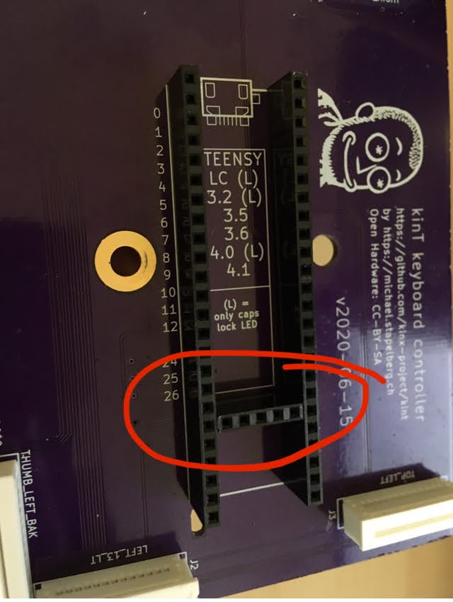
If no, I don’t understand what you mean with “underneath”?
Yes, i never did that :) sorry for the misunderstanding! Is the 3.3v pin the only relevant one? I'll try to fix this, but I think that should make everything work fine! Thanks for taking the time to help me find this and sorry again for missing the pins :/
Aha! No worries, glad we could figure it out :)
I’ll try to make this a little clearer on the page later.
Is the 3.3v pin the only relevant one
Yep, see the schematic: only the 3.3V pin of these is connected.
I would have preferred to get 3.3V from a normal pin (top/bottom rows of pins), but unfortunately the power output pins vary between Teensy++ and the newer ones, hence the need to use the horizontal pin row.
So it would be sufficient to connect the 3.3 output of my teensy to one of the horizontal holes with a short lead? Then I don't have to unsolder the entire teensy :)
Yes, that should be sufficient.
Great. Thank you very much again for your patience. I'll do that tonight, then report back. I'll try to get a good picture of the LEDs, so that maybe other people can see which way they should be oriented :)
Ah, speaking of: the marker should be at the cathode (and the white line on the silk screen is supposed to be the marker).
Is this what you’re seeing now that you fixed orientation?
If no, a good picture of your LEDs would be good to get some clarity on the marker situation :)
Thanks again for all the help, things work perfectly now.
The LEDs need to be oriented so that the two very small green stripes (that come around them from the underside) are oriented towards the side that has the | of the diode symbol. I think the |-- on the underside needs to point towards the |, I oriented it so that the | of the underside is on the same side as the | on the diode symbol initially, which was incorrect.
Thank you very much for your help, now I "just" need to come up with a decent keymap, but liberal use of the Compose key and macros seems to work fine ;) One more kb500 and then a kb600 to go, thanks for making this possible! [Sorry for the ugly soldering, just an image to see the LEDs close up]

The LEDs need to be oriented so that the two very small green stripes (that come around them from the underside) are oriented towards the side that has the | of the diode symbol. I think the |-- on the underside needs to point towards the |, I oriented it so that the | of the underside is on the same side as the | on the diode symbol initially, which was incorrect.
Yes, that all sounds right, and matches what the data sheet at https://www.kingbrightusa.com/images/catalog/SPEC/APT3216QBC-D.pdf describes. Maybe you haven’t seen that? I have included it directly in the soldering instructions now.

Yea, I didn't see that. Sorry, could have avoided all my problems by looking at the instructions more :/ but I think I have everything figured out now, thanks again!