This is software for ATMega32u4 or compatible AVR hardware USB chips that implements a standard-complying HID keyboard using only AVR-LIBC.
I used these for reference when coding:
- https://www.avrfreaks.net/forum/usb-initialization-problem
- https://www.pjrc.com/teensy/usb_keyboard.html
- https://www.usb.org/sites/default/files/documents/hid1_11.pdf
- https://www.avrfreaks.net/forum/help-properly-initializing-usb-hardware-atmega32u4
- https://www.beyondlogic.org/usbnutshell/usb1.shtml
- http://ww1.microchip.com/downloads/en/devicedoc/atmel-7766-8-bit-avr-atmega16u4-32u4_datasheet.pdf
- https://github.com/arduino/ArduinoCore-avr/blob/master/cores/arduino/USBCore.cpp
- http://sdphca.ucsd.edu/lab_equip_manuals/usb_20.pdf
Finished Board:
The ATMega32u4 controls the scanning matrix and the USB interface. I chose it because of its hardware USB interface and because it has enough I/O pins to support the whole keyboard without needing any multiplexing. It also has enough flash and SRAM for storing layouts. The 32u4 on the keyboard runs at 16mHz from an external crystal oscillator with 22pF load capacitors. It is powered directly from the USB lines with filtering capacitors.
Initially, I needed to test the main microcontroller circuit of the keyboard to ensure that it worked and that the USB worked, because I had developed on an Arduino Leonardo. (boards/ATMegaTestingBoard.brd)
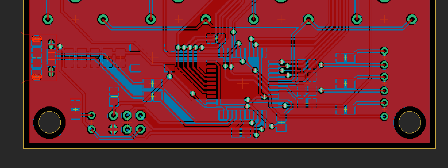
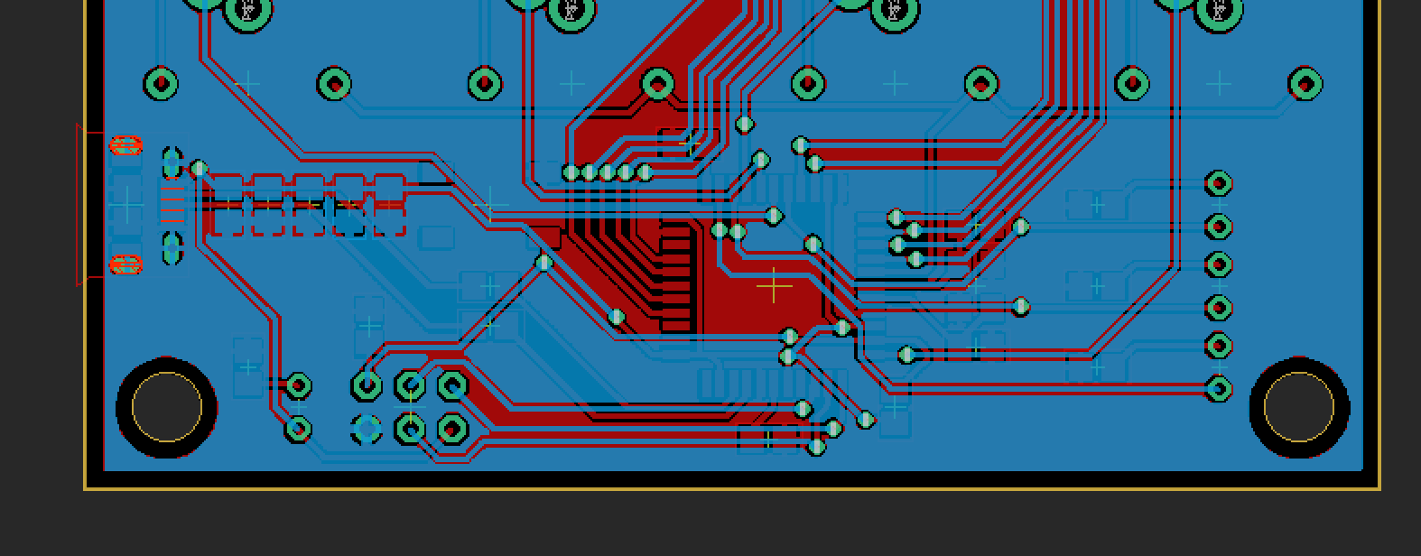
The portion of the board for the ATMega32u4 is fairly standard for this chip and is similar to the Arduino Leonardo, excluding the power regulators. It consists of the chip, the oscillator and load caps, the power and layer leds, the reset switch, the USB connector and data resistors, the ICSP pins, and the filtering caps on the underside of the board.
Top / Bottom (boards/Keyboard.brd):
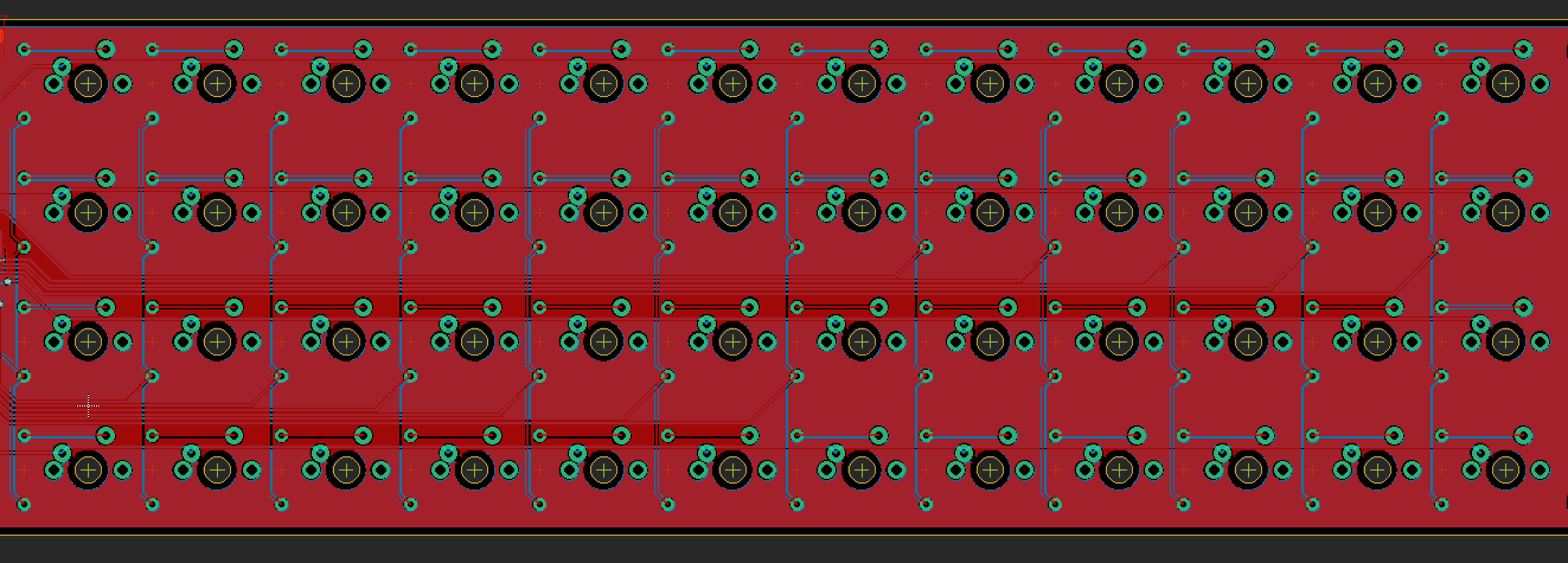
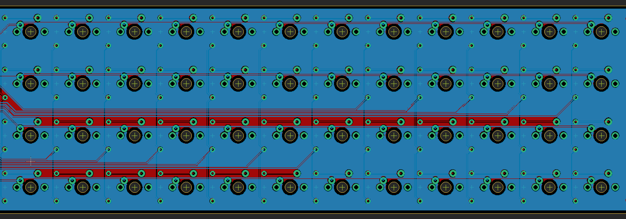
The rest of the board is the scanning matrix. The rows and columns use up the majority of the I/O on the chip. The matrix is standard for a keyboard - one pin of each switch in a column is connected through a diode to every other one in the column. Then, the remaining pin in each switch is common with the row. I used through hole diodes because they are much easier to solder. The switches are standard mechanical keyboard switches, and the footprints are from here: https://github.com/mknyszek/gateron-eagle To read the matrix, the row pins are pulled high through internal pull-up resistors. One column at a time is set low, so that a pressed key would pull the row pin low, signaling a key press at the current row and column index.
Top / Bottom matrix (boards/Keyboard.brd):
Assembling the board was straightforward except for the SMD components, specifically the TQFP ATMega32u4. It is really easy to bridge several pads very quickly, and completely ruin the chip. I soldered these by holding them in place and tacking down the corners so the chip didn’t move. I used a lot of flux, then with very little solder dragged the iron across the pins. The USB connector is also really difficult, I soldered the anchor pins and then the pins. It is really easy to bridge the pins with the ground enclosure. Using super glue after ensures that the connector doesn’t snap off when you unplug the cable.
First, the USB controller of the 32u4 is initialized. This is handled in the function usb_init(). The PLL (Phase Locked Loop) is initialized, taking the external clock as input. It runs at 48mHz and acts as the USB clock. After the USB controller is initialized, the control endpoint is set up and will receive setup packets from the host. The setup packets, handled in the ISR USB_gen_vect, elicit responses from the keyboard based on the values of bmRequestType and bRequest, which determine the type of request. After the host has requested and received the USB descriptors, and the keyboard has correctly responded to HID-specific requests, the host can enumerate the device and use it as an input device.
The key repeat feature of modern keyboards is handled separately from the standard functions usb_send() and usb_send_keypress(). If a key is held down for some period of time, it should be repeated until it is released. This is taken care of in the ISR USB_gen_vect, specifically when the SOFE (start of frame) bit is set. This interrupt triggers at 1kHz, which is how often the host sends start of frame packets. If no keypresses have been generated since the period time, which is kept track of with keyboard_idle_value and current_idle, the entire HID report is resent to facilitate key repeat. The period of time the device should wait before resending the report is set from the wValue in the HID request SET_IDLE.
The scanning matrix of the keyboard uses the current sourcing and internal pullups of the I/O ports on the 32u4. Because of the orientation of the diodes, the columns of the keyboard are set low when they are going to be read. The rows are always pulled up, meaning that if a key is pressed, it will be pulled low because the switch is connecting the row and columns. The matrix scanning is repeated quickly, and changes in key state are recorded in the six-byte USB HID report. The report is six bytes to support six concurrent key presses. The keyboard dynamically assigns and removes keys from the report to support 6-key-rollover, and it also resets the reports on layout layer shifts to prevent strange glitches. The meta and special keys like CTRL, ALT, and SHIFT have their own byte apart from the report, where each bit represents a different key. This is according to the USB HID Spec.
The rows and columns of the recorded keypresses are translated into actual keycodes from the specified layout in layout.h. The layout is written from the standard HID keycodes in keys.h. Because the keyboard does not have enough physical keys to support all the letters, function, and number keys, some keys are macros that change the mappings of all the keys. These keys are handled separately and do not generate keypress events on their own. Rather, they update the current layer that the scanning matrix is reporting keypresses from to change the keycodes.
- Changing the routing on PORTD to make it iterable, making the code more readable and cleaner.
- Using USB-C instead of micro b, meaning that you would not need a dongle for use with newer macs. This would, however, make it much more difficult to solder and the PCB more complicated, since the USB-C connectors have 24 pins.
- Using the BGA package for the ATMega32u4 so that it could fit in between switches on the underside of the board, meaning that the PCB would only have to be as big as to fit the switches. This would make it more compact.
- Using symmetrical keycaps so that the keycaps aren’t skewed when using keyboard layouts other than QWERTY.
- Adding support for a dedicated FN key endpoint and Caps lock and num lock; currently you have to remap function to media keys with a third party tool for the media keys on the keyboard to work on touch bar macs.
- Move the ICSP connector down, right now you have to bend the power LED up for the connector to make contact with the headers.
- Route the third layer led to a different I/O port, right now only two of the three LEDs work.


