Table of Contents
- Introduction
- I: Motion Control.
- II: Planar Laser RangeFinder.
- III: Navigation and Localization
- Robotic arm
- Encountered problems and solutions
- Conclusion.
- Bibliography
University of Burgundy
Robotic Engineering 2 - ROS PROJECT
Report
Authors
Sylwia Bakalarz
Arsanios Mickael
Lasse Mackeprang
Supervisors
Ralph SEULIN
Marc BLANCHON
Raphael DUVERNE
Thibault CLAMENS
First Objective. : Motion Control.
Second Objective. : Planar Laser RangeFinder.
Third Objective. : Navigation & Localization.
Fourth Objective. : Robotic Arm.
The purpose of the project was to familiarise with a unified and open source programming framework for controlling robots, which is ROS. The First phase of it was to learn the basic concepts, work on tutorials and practice.
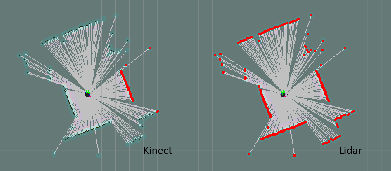
In the Second phase, by implementing the acquired knowledge, we learned how to control a mobile base at different levels of abstraction. We began with motor drivers and wheel encoders, and proceeded upward to path planning and map building. Secondly we switched from kinect visual sensor to rplidar and tested its efficiency in building a map. Finally, with the help of available resources, turtlebot2 could be navigated in a known map either by selecting 2D Navigation Goals in Rviz or running a custom created script with hard coded positions in the map. Navigation in the known map included obstacle avoidance.
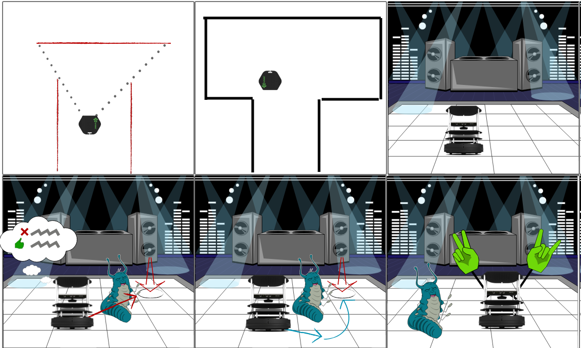
Third phase of the project focused on PhantomX Pincher Robot Arm. Robotic arm was fixed on a table with a kinect camera. The scenario for was called “Pick and Place” like shown in the storyboard.
Each part of the project was implemented through packages, python scripts and custom launch files.
Node: : A computational process. Nodes communicate with each other using topics or services. ’rosnode’ is a command that displays information about the nodes.
Topic: : A channel through which messages travel. Nodes publish/subscribe to topics.
Messages: : Instructions published by nodes to topics.
Master: : It is essential for the nodes to locate one another.
rosout: : The console log reporting mechanism in ROS.
roscore: : A command that activates a master with essential components.
ROS is an open-source Robot Operating System -> robotic middleware. It provides services including hardware abstraction, low-level device control, implementation of commonly-used functionality, message-passing between processes, and package management. It also provides tools and libraries for obtaining, building, writing, and running code across multiple computers.
A node publishes a message to a given topic, another node can subscribe to the topic and perform some operation. There may be multiple concurrent publishers and subscribers for a single topic, and a single node may publish and/or subscribe to multiple topics. In general, publishers and subscribers are not aware of each others’ existence.
Communication using topics is not always the best solution as the data has to be constantly published. Another solution is provided by services, which is request/reply based. A providing node offers a service under a name and a client uses the service by sending the request message and awaiting the reply.
Bags are an important mechanism for storing data, such as sensor data, that can be difficult to collect but is necessary for developing and testing algorithms.
-
mbot_motion
-
dependencies
-
rospy: Python client library
-
actionlib: api for preemptable tasks like moving the base to a target location
-
visualization_msgs: visualizing markers in rviz
-
tf: keep track of multiple coordinate frames over time
-
geometry_msgs: messages for common geometric primitives such as Twist
-
-
imported
- transform_utils from rbx1 for Quaternion angle conversion
-
-
mbot_nav
-
dependencies
-
turtlebot_navigation: demos of map building using gmapping and localization with amcl, while running the navigation stack.
-
turtlebot_gazebo: 3d environment simulation for turtlebot.
-
frontier_exploration: frontier based exploration of unknown environments extending on the existing navigation stack.
-
-
modified
-
amcl.launch from turtlebot_navigation
-
takes a bool argument “onlaptop” to determine if the launch file is run from workstation or turtlebot(laptop)
-
3d sensor scan topic is changed to kinect_scan to prevent interference with lidar scan topic
-
default map is set to the lab map
-
loads a modified Move base launch file
-
-
move_base.launch.xml from turtlebot_navigation
-
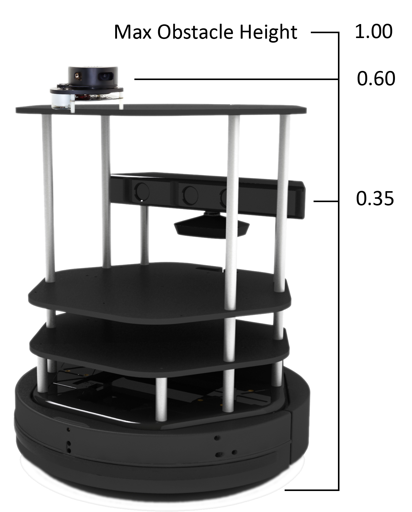
loads a modified common_costmap_params.yml, with map_type as costmap instead of voxel to match lidar scan data and max_obstacle_height as 1.0 instead of 0.35 inside the obstacle layer to compensate for the lidar height from the ground, inflation_radius was reduced to 0.3 from 0.5 this made the autonomous navigation easier in narrow passages
-
loads modified local_costmap_params.yaml, map_type was changed to costmap instead of voxel to match lidar scan data, and the map size was changed to 6x6
-
loading modified global_costmap_params.yaml, map type was changed to costmap instead of voxel to match lidar scan data
-
-
-
created
-
Two maps were generated, one using lidar scan data, and the other using kinect, subsequently the lidar map was cleaned and adjusted
-
dance.py: A navigation script with hardcoded navigation points in the lab map
-
auto_mapping.launch: A Launch file for frontier exploration with optional simulation, turtlebot gmapping, modified move with custom planner configuration to disable recovery protocols
-
explore.launch.xml that contains the default client and a server with the modified common_costmap_params.yml.
-
simple_explore_client.py A script to run unbounded exploration
-
-
The room is setup so that each Workstation is paired with a Turtlebot. The Workstation is connected to the internet via Ethernet, while the Turtlebot has to be connected to an access point if internet is needed. The Workstation and Turtlebot are connected to an additional private network over a wireless router placed on the Turtlebot itself, this network is used by ROS. On every private Turtlebot network, the Workstation has a static IP 192.168.0.100 and the Turtlebot’s IP 192.168.0.200.
On the Workstation it is important to set correct environment variables. This depends on where roscore will be running, ROS_MASTER_URI can be set to URI of the master by running export ROS_MASTER_URI=<URI> or permanently by appending the same line to the .bashrc file on the Workstation.
Inside your catkin_ws/src folder
git clone --recurse-submodules https://github.com/koalasession/BSCV5_RobEng2.git
then in your catkin_ws folder.
catkin_make
Low level motion control is giving the robot a speed, angle and angular velocity. This level of commands to the robot does not care about odometry, the robot does not know where it is or how much it moved.
ROS uses the Twist message type for publishing motion commands. The topic to which it publishes messages is called cmdvel (“command velocities”). The base controller node subscribes to the /cmdvel topic and translates Twist messages into motor signals that turns the wheels.
To move straight ahead with a speed of 0.1 meters per second would require a Twist message with linear values x=0.1, y=0 and z=0, and angular values x=0, y=0 and z=0. Twist message can be sent on the command line, the message part would take the form:
`{linear: {x: 0.1, y: 0, z: 0}, angular: {x: 0, y: 0, z: 0}}`
The larger the angular z value compared to the linear x value, the tighter the turn.
More efficient way of sending the messages is by using nodes, which can be created within a ROS package with the following dependencies: rospy, geometrymsgs.
In this part of the project odometry information was used to determine the distance that has been travelled. The odometry controller, which publishes all its information into the transform tree, which is accessible using the Transform Library, has to be running.
The a ROS package was required the following dependencies: rospy, geometrymsgs and tf.
This part of the project’s was to navigate turtlebot to move in a square using Twist messages and odometry.
Odometry estimation of displacement is added layer on top of Twist. Information gathered to control the base concerns not only linear and angular velocity but also displacement and orientation.
Odometry used data from motion sensors to estimate change in position over time or estimate the relative position to a starting location. The method appeared to be inaccurate due to the inadequate update frequency or measuring errors.
    # Loop for 4 side of the square.
    for i in range(4):
        # creates a Twist message with linear values.
        msg = Twist()
        msg.linear.x = linear_velocity
        # Get the starting position values
        (position, rotation) =
        get_odom(tf_listener, odometry_frame, base_frame)
        x_start = position.x
        y_start = position.y
        # Keep track of the distance traveled
        distance = 0
        # publish until the goal distance is reached
        while distance < goal_distance:
            pub.publish(msg)
            rate.sleep()
Move base is a layer on top of odometry. Turtlebot2, given a location and orientation on the map(if there were no dynamic obstacles), can find the path and moves towards it automatically.
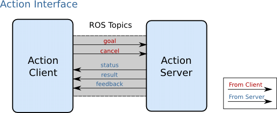
The actionlib stack provides a standardized interface for performing tasks. Like for example, moving the base to a target location or performing a laser scan.
The action client and server communicate with each other using a predefined action protocol. This action protocol relies on ROS topics in a specified ROS namespace in order to transport messages.
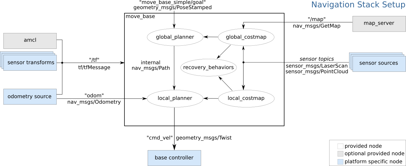
The movebase package provides an implementation of an actionlib package that, allows the turtlebot2 to reach a navigation goal. The movebase node links together a global and local planner to accomplish its global navigation task. The movebase node also maintains two costmaps, one for the global planner, and one for a local planner (see the costmap2d package) that are used to accomplish navigation tasks.
The movebase node provides an implementation of the SimpleActionServer that takes in goals containing geometrymsgs/PoseStamped messages. The recommended way to send goals to movebase is by using the SimpleActionClient (allows tracking the status).
Navigating a square using move base
 # Initialize a counter to track waypoints
    i = 0
    # Cycle through the four waypoints
    while i < 4 and not rospy.is_shutdown():
        # Update the marker display
        # self.marker_pub.publish(self.markers)
        # Intialize the waypoint goal
        goal = MoveBaseGoal()
        # Use the map frame to define goal poses
        goal.target_pose.header.frame_id = 'map'
        # Set the time stamp to "now"
        goal.target_pose.header.stamp = rospy.Time.now()
        # Set the goal pose to the i-th waypoint
        goal.target_pose.pose = waypoints[i]
        # Start the robot moving toward the goal
        self.move(goal)
        i += 1
roslaunch turtlebot_bringup minimal.launch
rosrun mbot_motion <script_name>.py
Available scripts: move.py, twist_square.py, move_odometry.py, move_odometry_square.py, move_base_square.py
For the move base any empty map should be provided
roslaunch turtlebot_navigation amcl_demo.launch map_file := `rospack find rbx1_nav`/maps/blank_map.yaml
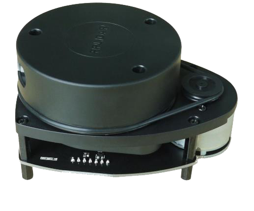
A low cost LIDAR sensor suitable for use in indoor SLAM operation. It provides a 360 degree scan field with a guaranteed range of 8 meters. RPLIDAR supports full integration with ROS and has multiple packages ready to use.
Under ideal conditions:
-
12 meter range
-
8000 samples/second
-
1 degree angular resolution
-
0.2 cm distance resolution
-
2-10 hz rotation frequency
-
Price 99$ (dfrobot.com)
The LIDAR can be used out of the box with minimal setup by downloading and installing the packages rplidar_ros and turtlebot_le2i. In the catkin_ws/src directory clone and build.
git clone https://github.com/roboticslab-fr/
rplidar-turtlebot2.git
-
roslaunch turtlebot_le2i rplidar_3dsensor.launch is a copy of turtlebot_bringup 3dsensor.launch with the scan topic remapped to kinect_scan
-
The lidar can be used with the ROS by example code (refer to vol. 1 chapter 8.5 and 8.5.2) to transverse a known map.
roslaunch turtlebot_le2i remap_rplidar_minimal.launch
roslaunch rbx1_nav tb_demo_amcl.launch map:=<map_name>.yaml
rosrun rviz rviz -d `rospack find rbx1_nav`/nav_test.rviz
There are a lot of useful things we can figure out by looking at the turtlebot_le2i package regarding how the LIDAR setup is performed, and since it worked on our Turtlebot there are a lot of things we can use straight from this package. Some important aspects when creating your own package are the URDF files used to describe the robot. This includes its dimensions, placement of sensors, frames of references and kinematics. The urdf file is written in XML format, which can be simplified using a xacro, and is used to describe where the LIDAR is placed and its size, we can most likely just use the rplidar.urdf.xacro provided by the package installed and used to test the laser. The launch files can be edited to launch only the things we need and again the bringup files from the downloaded package can be a nice reference.
After generating a map, the turtlebot localizes itself using the navigation stack against the map. When the turtlebot receives a destination goal, a path planner creates a global path to the destination. Along the way it provides short term goals, which help to avoid obstacles and adjust the speed, and angular velocity. In case the robot gets stuck a recovery behaviour is performed. There are two ways of exploring an environment, using teleoperation with different input devices, or autonomous mapping like frontier exploration
roslaunch turtlebot_le2i rplidar_minimal.launch
roslaunch turtlebot_le2i rplidar_3dsensor.launch
roslaunch turtlebot_navigation gmapping_demo.launch
roslaunch mbot_nav navigation_joystick.launch
To create the map we have to use the map_server ROS node. This node offers map data as a ROS service and also provides the map_saver utility which allows dynamically generated maps to be saved to file. The basic usage of map_server is as follows:
rosrun map_server map_saver -f /tmp/my_map
The saved map is written to two files. A .yaml file that describes the map meta-data and points to a .pgm image file. The image file can be viewed and edited to clean up the map by removing unwanted pixels or close off sections using black lines. A map can also be created from Bag data.
We can say that the navigation stack consists of layers of packages each one providing an additional level of abstraction. The job of navigation stack is to produce a safe path for the robot to execute, by processing data from odometry, sensors and environment map. Understanding the configuration and different parameters of the configuration stack is crucial to minimize the amount of time spent on development and the performance of the algorithm or strategy.
The global navigation is used to create paths for a goal in the map or at a far-off distance The local navigation is used to create paths in the nearby distances and avoid obstacles, for example, a square window of 4 x 4 meters around the robot.
The costmap package builds a 2d Occupancy Grid like a map, and inflates costs in a 2D costmap based on the occupancy grid and a user specified inflation radius. Global costmap is generated by inflating the static map provided by the map server in the navigation stack, the inflation radius is relative to the footprint of the robot and user specified parameters. Local costmap is generated by inflating obstacles detected by the robot’s sensors in real time.
Footprint is the contour of the mobile base. In ROS, it is represented by a two dimensional array of the form [x0, y0], [x1, y1], [x2, y2], ...]. This footprint will be used to compute the inflation of obstacles in a way that fits this robot. Usually for safety, we want to have the footprint to be slightly larger than the robot’s real contour. To determine the footprint of a robot, the most straightforward way is to refer to the drawings of your robot.
The costmap automatically subscribes to sensors topics over ROS and updates itself accordingly. Each sensor is used to either mark (insert obstacle information into the costmap), clear (remove obstacle information from the costmap), or both. A marking operation is just an index into an array to change the cost of a cell ranging from 0 to 255.
Inflation is the process of propagating cost values out from occupied cells that decrease with distance. For this purpose, there are 5 levels of costmap values:
-
Lethal : meaning there is definitely an actual obstacle that will result in certain collision
-
Inscribed : means that a cell is less than the robot’s inscribed radius away from an actual obstacle. So the robot is certainly in collision with some obstacle if the robot center is in a cell that is at or above the inscribed cost.
-
Possibly circumscribed : similar to inscribed, but using the robot’s circumscribed radius as cutoff distance. Thus, if the robot center lies in a cell at or above this value, then it depends on the orientation of the robot whether it collides with an obstacle or not.
-
Freespace : assumed to be zero, and it means that there is nothing that should keep the robot from going there
-
Unknown : there is no information about a given cell
Assigning a value between “Freespace” and “Possibly circumscribed” depends on their distance from a “Lethal” cell and the decay function provided in the configuration To see the local costmap in rviz set the topic to:
/move_base_node/local_costmap/costmap
To see the global costmap in rviz set the topic to:
/move_base_node/global_costmap/costmap
AMCL is a ROS package that deals with robot localization in relation to a map, it uses a laser scanner and transform messages to estimate location on a map. The localization is integrated in ROS by emitting a transform from a map-frame to the odom frame that “corrects” the odometry. To query the robot position according to the localization you should ask the transform of base_footprint in the map frame. This is different from dead reckoning, Odometry based robot navigation means how to make use only of the odometry to understand where the robot is. That is dead reckoning navigation.
The scan topic of 3dsensor inside amcl.launch file was changed to kinect_scan to avoid flickering of the scan topic between Lidar and Kinect
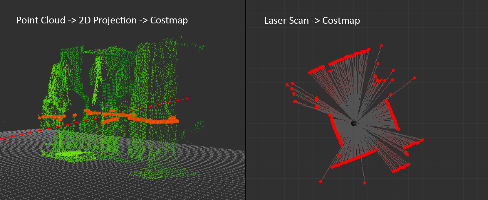
map_type is set as costmap instead of voxel to match lidar scan data. Voxel map type is a 3d Point cloud that is projected to 2D and then translated to the costmap, the Lidar scan data can be translated directly to costmap.
max_obstacle_height is set to 1.0 instead of 0.35 inside the obstacle layer because the Lidar height from the ground is greater than the Kinect’s height. Otherwise the Obstacle layer will not record any obstacles.
on Turtlebot
roslaunch turtlebot_bringup minimal.launch
roslaunch turtlebot_navigation amcl_demo.launch map_file:=/home/turtlebot/ros/indigo/catkin_ws/src/milanobot/mbot_nav/maps/map_lidar.yaml
on Workstation
roslaunch turtlebot_rviz_launchers view_navigation.launch
In a completely unknown environment, a robot’s task is to explore the area and make a map. It set navigation goals along the way according to the map and the robot position. An algorithm and a strategy is developed in order to correctly explore and map unknown parts of the map.
Frontier expliration is a ROS package made for exploring unknown environments and neeeds a map server running to update itself. Executing a frontier exploration task can be achieved by a user-defined polygon area either through rviz or ExploreTaskAction service. The exploration goal contains an initial point to start exploration, and a polygonal boundary to limit the exploration scope. To run an unbounded exploration task, simply leave the boundary blank.
The script in python for Frontier Exploration:
client = actionlib.SimpleActionClient(
        'explore_server',
        ExploreTaskAction)
    client.wait_for_server()

# empty polygon
polygonStamped = PolygonStamped()
polygonStamped.header.frame_id = 'map'
polygonStamped.header.stamp = rospy.Time.now()
# starting point from turtlebot position
initialGoal = PointStamped()
initialGoal.header.frame_id = 'map'
initialGoal.point = Point32(x=0, y=0, z=0)

# unbounded exploration, uncomment for bounded
# for x, y in zip(self.points_x, self.points_y):
#    polygonStamped.polygon.points.append(
#        Point32(x=x, y=y, z=0))

# setting exploration goal
exploration_goal = ExploreTaskGoal()
exploration_goal.explore_boundary = polygonStamped
exploration_goal.explore_center = initialGoal

# starting exploration
client.send_goal(exploration_goal)
-
The package is buggy and has been updated in later versions of ROS
-
In environments that contain a lot of small width objects like chair and desk legs, the navigation behaves in an erratic way
-
Initial clearing with a Twist rotation message is required to avoid immediate failure
-
Recovery protocols are disabled to avoid random clearing with no necessity
-
This package with Lidar is better used in walls only environment or a closed maze
roslaunch turtlebot_le2i rplidar_minimal.launch
roslaunch mbot_nav auto_mapping.launch
roslaunch turtlebot_rviz_launchers view_navigation.launch --screen
The PhantomX Pincher Robot Arm is a 4 degree-of-freedom robotic arm, easily added to the ROS platform. It has a range of 30 centimeters from its base and consists of 5 actuators in frame and an ArbotiX Robocontroller for on-board processing. The gripper can lift up to 250 grams. The arm was already assembled when we started to work on it, and it had been set up on a table with a top view from a kinect.
For the arm to be able to pick up a cube, the arm had to be calibrated to obtain a transform in relation to the kinect. This process just required a correct setup.
A printed checker-board input underneath the camera in range of the arm, and the following two files were launched:
roslaunch turtlebot_arm_bringup arm.launch
roslaunch turtlebot_arm_kinect_calibration calibrate.launch
Once the camera has located the checker-board a picture popped-up with four corners of the checker-board marked with numbers. The edge of the left side of the gripper was then put on the number specified by the console, and you follow it’s directions. Once the steps were done, the transform was printed to copy. This transform can be put in the block_manip_complete.launch file:
<node pkg="tf" type="static_transform_publisher"
name="static_transform_publisher"
args="0.16642 -0.152942 1.00053 -0.344048 0.394775 0.610077 0.594633 /base_link /camera_link 100"/>
or published to a topic:
rosrun tf static_transform_publisher -0.26683
-0.122903 -0.537733 0.5 -0.499602 0.5 0.500398
/arm_base_link /openni_camera 100
After the calibration the demo, which includes bringups for everything needed, such as the Robot Arm, MoveIt!, kinect, block manipulation and RViz, could be launched:
roslaunch turlebot_arm_block_manipulation
block_manip_complete.launch
mbot_arm
In turtlebot_arm_block_manipulation/demo/block_manip_complete.launch under the kinect bringup the following argument was added:
- <arg name=“depth_registration” default=“true” />* This makes the kinect start up with the factory calibration of the depth camera and fixes the skew between the colour and depth images.
In turtlebot_arm_block_manipulation/src/block_detection_action_server.cpp
#include <ros/package.h>
std::string path = ros::package::getPath
("turtlebot_arm_block_manipulation") + "/pcd_files/";
was added and all static references to the mscv user was replaced by this path. The directory was added to the package as well. This ensured that no matter which user runs the launch file the pcd-files will be saved in a directory in this package. RVis could then be launched with it’s ”Fixed Frame” reference being the robot arm’s ”base_link”, which was solely a cosmetic change.
Integration with turtlebot
The package is used for the robot arm to pick up a green cube from a turtlebot when it transmits a message to a specific topic. This could be after a successful rendezvous, alternatively the scanning process can be started manually by publishing to this topic:
rostopic pub -r 1000 /relay/robot_status2 std_msgs/String
"vsdone"
This message starts a scan. After a cube is found the colour of the cube is checked. Once a green cube has been found, the pick and place program is started and in return, it picks up the cube from the turtlebot and puts it at a hard-coded place on the table. The program is then terminated.
-
Permissions for read writing and executing has to be enabled for the arm to work:
sudo usermod -a -G dialout userworks best on a mono colour surface, as it will be easier to detect the colour of the cube
Result Managed to pick up a cube after manually transmitting the ”vsdone” message we had the potential to work further on incorporating the arm in our project if time allowed. The modified package can be found inside mbot_arm.
-
In the BSCV5_RobEng2 repository mbot_arm is a reference to another github repo. To include the repository when cloning add –recurse-submodules as an option:
git clone --recurse-submodules https://github.com/koalasession/BSCV5_RobEng2.git
-
The Turtlebot would behave erratically and th tf tree would break, this error was not easy to detect, the solution was to restart the kobuki base itself.
-
Getting stuck: The turtlebot can get stuck even after performing the basic recovery protocol.
-
Reality vs simulation: there are factors in real life that are not simulated. eg: the nature of the ground and its bumps.
-
Inconsistency: The navigation doesn’t have a memory, the same destination can have different paths each time and sometimes a previously crossed door can be perceived as blocked.
-
Compatibility: Some packages are designed for different robots.
-
configurations: The subscribed topics and other configuration can be different from package to package.
-
Robotic arm: the main demo block_manip_complete.launch did not work as a “pcd input/output error” would occur. The problem was that in the block_detection_action_server.cpp, the path, where some files where being written to, was hardcoded to a specific user ”mscv”, and since we use the bscv user the path would not be available. After the path was changed to a valid location the launch was successful and the scan for a block can be started.
-
Robotics arm: When viewing the depth and colour-image through Rviz, the two would be skewed and the detected cube would not have the right colour, because the found cube would seem the colour of the table next to the cube. This problem was solved with an easy fix. As it turns out, the factory calibration of the kinect can be used, a setting which is not enabled by default, and this fixes the skew. Most of the time working with the robot arm was spend solving these problems.
Maximizing the performance of the navigation stack required some fine tuning of parameters. The process included a lot of tries and mistakes in order to finally agree on the most optimal solution. Apart from the basic gmapping and navigating in a know map we tried to implement “Frontier exploration” with some success, but in the classroom conditions it appeared to be unreliable. In general, we often found ourselves in need to restart the base of turtlebot as some unexpected errors came up.
ROS by example vol. 1, R. Patrick Goebel Leslie Lamport, * 8.4 Map Building using the gmapping Package - ROS by Example vol. 1*, R. Patrick
Goebel ROS wiki, https://wiki.ros.org Gmapping,
http://wiki.ros.org/gmapping Lidar,
https://www.slamtec.com/en/Lidar/A1 Robot arm,
https://www.trossenrobotics.com/p/PhantomX-Pincher-Robot-Arm.aspx ROS Frontier exploration.
http://wiki.ros.org/frontier_exploration Kaiyu Zheng ROS Navigation Tuning Guide.
http://kaiyuzheng.me/documents/navguide.pdf Giorgio Grisetti Introduction to Navigation using ROS.
https://www.dis.uniroma1.it/~nardi/Didattica/CAI/matdid/robot-programming-ROS-introduction-to-navigation.pdf Robotic arm package.

