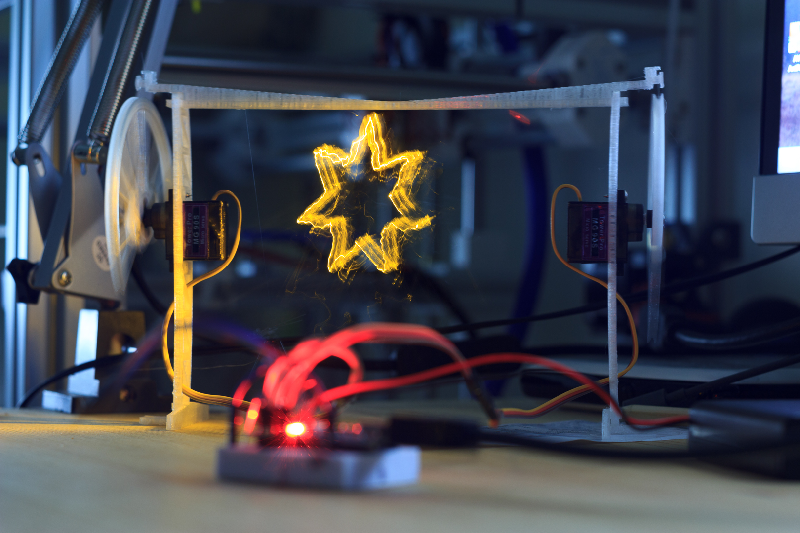
A minimal lightpainting robot, using two servos driven by an Arduino mounted to a 3D-printed scaffolding and moving an LED suspended by fishing line.
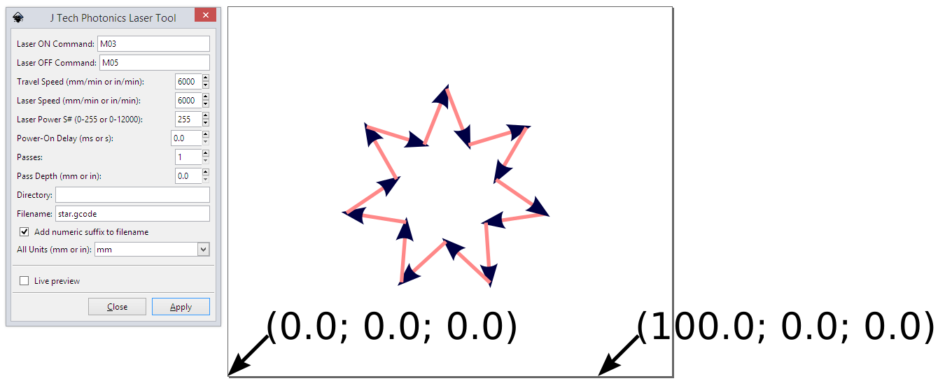
It can draw small shapes created in Inkscape using a GCODE format like a laser cutter. Take a long exposure photograph in a dark room to reveal the drawing.
- Arduino nano or similar
- A 5V power supply (3xAA batteries will do for 4.5V)
- 2x
90Smicro servo (metal gear version preferred, e.g.MG 90S) - small breadboard and jumper wire
- bright 3mm LED and appropriate resistor
- fishing line (thin, flexible, strong, plastic thread)
- thin wire to connect LED
- small counterweight, such as a magnet or coin
- Blue-Tack or similar to hold various things in place
- 3D printed parts (2x
gear, 2xfoot, 2xstand, 1xbeam)
Clip the foot to the stand, and push in a servo so that the arm is outside,
as shown in the image above. Secure it with the top screw.
Repeat for the other side, then connect the two sides with the beam.
Fit a gear to each servo by removing the screw that holds the arm, clipping
the 3D printed part onto the arm, and securing it again with the screw.
You may need to take the arm off entirely to align it with the servo end positions. The gear should be vertical at the end stops.
Cut two lengths of the fishing line to about 50cm. It can be shortened later!
Tie one end to the gear and secure with blue tack to ensure it goes into the ridge when the gear turns.
Solder the thin wire to the LED and insulate with e.g. electrical tape.
Use Blue-Tack to hold together the LED and counterweight, and somehow connect it to both fishing lines. When both sides are most extended, it should hover close to the ground, horizontally centered in the frame.
I haven't got a good solution for this part yet, I insulated the LED with electrical tape, and sandwiched it with more Blue Tack and the fishing lines between two small coins as counterweight.
Make the connections on a breadboard using the jumper wires.
Servos:
brown->GND(if using a battery or external supplies, also connect its ground to the Arduino'sGND)red->5V(battery or external power supply recommended)yellow->D2(left) andD3(right)
LED:
LED Anode->D11LED Cathode->GND
Upload the Arduino sketch.
Open a serial monitor (Arduino IDE) at 115200 baud. You should see a
Hello World message.
You can send GCODE commands on the serial connection, and this is also how the more complex shapes will be drawn.
Write M03 to turn the LED on, and M05 to turn it off.
Try e.g. G1 X20 Y20 to move to that position, and e.g. G1 F600 to change the
feed rate (how fast the servos move).
See shapes/ for an example SVG file and corresponding GCode.
I used Inkscape to draw the shape (convert to path) and the JTech Photonics Laser plugin to generate the GCODE.
Set the document unit to mm and the size to 120mm width, 100mm height.
Copy and paste the generated GCODE into a serial terminal to draw the shape.

