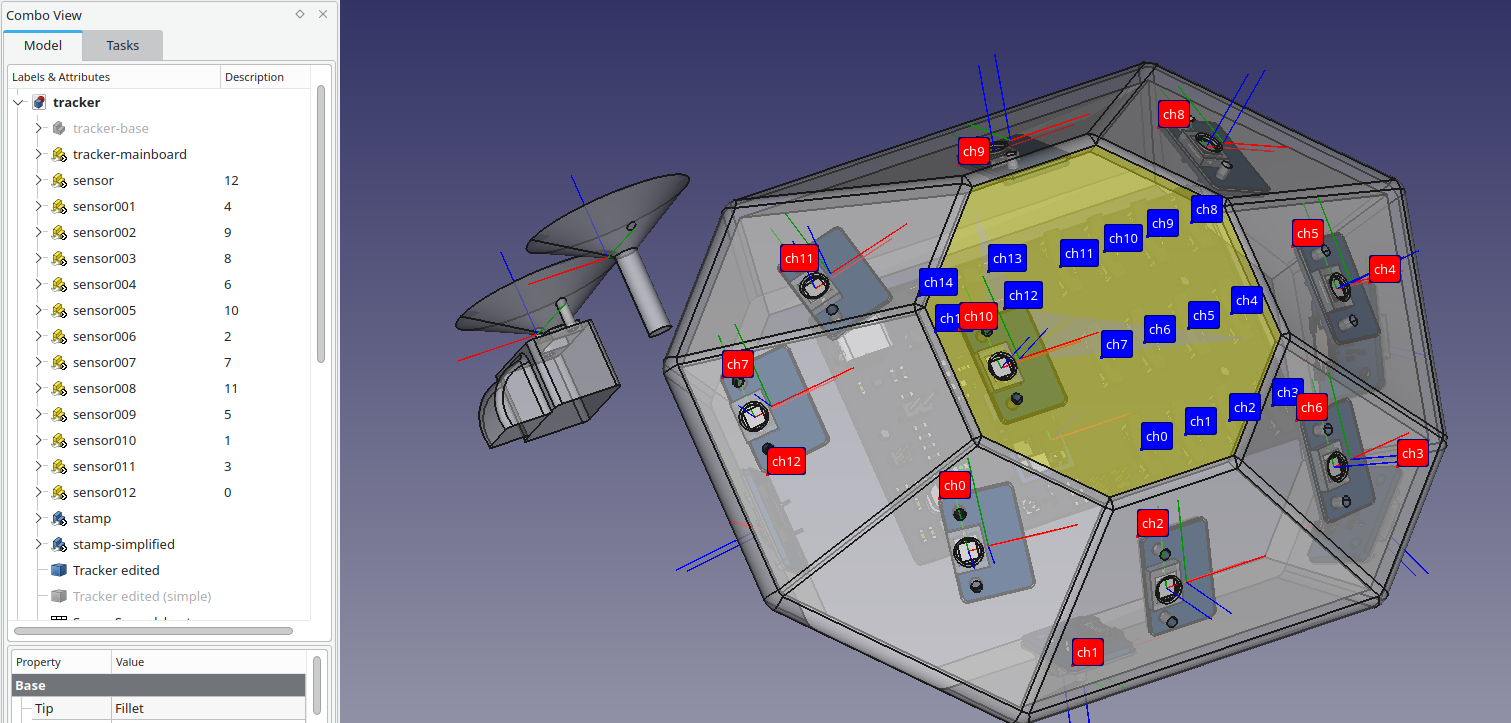
This repository contains a SteamVR tracker CAD files and helper scripts to create and edit a such tracker Also provides script for for building a JSON configuration file with sensors placement. The tracker is created around Tundra Labs TL448K6D-VR SIP.
Design of mainboard and sensor boards is available in a separate repository Periscope-hw.
- FreeCAD (both mainline and FreeCAD-Link should work fine)
- OpenSCAD
- python3-pivy2
- Start FreeCAD
- Create a sensor support Body
- Add sensor models, and a mainboard model
- Add a stamp model
- Copy
sensor-builder.pyinto FreeCAD Python console and runplace_cut_sensors() - Sensors will be placed on the support body surface and near area will be cut with a the stamp
- Use
sensor-extraction.pyfor creating JSON configuration file. It expects channel map set as sensor Label2 attribute (see the screenshot above).
- Create a Part Design Body representing sensor support shape, set "tracker-base" label
- Import sensor as link (App::Link), repeat for next sensors - in the tree, you should see "sensor", "sensor001", "sensor002"... This can be done by opening sensor file in a new tab, and selecting it in the tree. Then you should switch back to the tracker assembly clicking on its tab and use Make link to create a link.
- Import (as link) "stamp" single time. FreeCAD will reuse it.
- Import (as link) "tracker-mainboard".
- Place sensors near to "tracker-base" surface, outside.
- Run place_cut_sensors() - it will find closest point on the support shape surface for every sensor, move sensors and prepare support places.
You can do a manual adjustment of a sensor placement, after this use
recut_sensors()to recreate support places. You can save (in a spreadsheet object) adjustments values withsave_corr()and load them withload_corr()Finallyplace_cut_sensors(True)andrecut_sensors(True)uses "stamp-simplified" for cutting shape. This is useful for creation of simpler shape for simulation. - You may use a newly created shape "Tracker edited" as base to work. Select it and create a Part Design Body. The shape will be used as BaseFeature.
- You may export "Tracker edited (simple)" as OpenSCAD .scad model for simulation with SteamVR HDK tools. I recommend tuning of export precision. To do this: select the OpenSCAD workbench, then open Edit->Preferences->OpenSCAD and adjust Triangulation setting. 0.2 seems to be good starting value.
"sensor" should have to two LCS-es (local coordinate system): "LCS-Base" (for placing on the "tracker-base" surface) and "LCS-Diode" (used in sensor-extraction.py) "stamp" and "stamp-simplified" need "LCS-Base" that will be aligned with a sensor one.
If you are stuck somewhere, please check the raw design process video:
The script extracts sensors and mainboard's IMU placement to JSON configuration file. It it independent from sensor-builder.py but requires:
- sensors imported as links, every sensor have to contain "LCS-Diode". The LCS is used for getting diode placement and normal vector,
- mainboard imported as link, with "LCS_IMU" for IMU (inertial measurement unit) placement.
Before running the script, set channel map for every sensor. Just edit Label2 (clicking in the tree view, under the Description column, and pressing F2) for every sensor link. Notice blue labels in the screenshot above. They show channels for the mainboard sockets. After setting Label2, you can run the add_sensor_labels.py to add red labels for sensors. They are completely optional.
Notice:
"sensor_env_on_pin_a":"0x7FFFF800"
in the created JSON. This is needed because the SIP pins for sensors 1-11 (channel map 0-10) are reversed.
Check LICENSE for details.

