(Part in need of a revision)
Core packages for the LAR DEMUA Atlas Project:
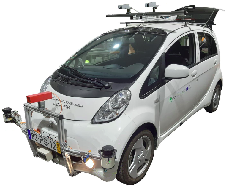
The Atlascar2 is an instrumented vehicle used for scientific research in the areas of Autonomous Driving and Driving Assistance Systems. It contains significant computing power onboard which is used to process the data streaming from several sensors.
The set of sensors mounted onboard varies according to the needs of the researchers. Nonetheless, there are a few core sensors which are always available:
| Name | Type | Range (m) | Resolution (px) | Frequency (Hz) | Description | IP address |
|---|---|---|---|---|---|---|
| left laser | LIDAR, Sick LMS151 | 80 | --- | 50 | Mounted on the front bumper, near the left turn signal. | 192.168.0.5 |
| right laser | LIDAR, Sick LMS151 | 80 | --- | 50 | Mounted on the front bumper, near the right turn signal. | 192.168.0.4 |
| front laser | LIDAR, Sick LD MRS | 200 | --- | 50 | Mounted on the front bumper, at the center. Four scanning planes. | 192.168.0.6 |
| top left camera | Camera, Point Grey Flea2 | --- | 964x724 | 30 | Mounted on the rooftop, to the left. | 169.254.0.5 |
| top right camera | Camera, Point Grey Flea2 | --- | 964x724 | 30 | Mounted on the rooftop, to the right. | 169.254.0.4 |
| gps | Novatel GPS + IMU | --- | --- | --- | Mounted on the rooftop, to the back and right. | --- |
-
Step 1: Turn on the car.
-
Case 1: When the car is stopped:
- Step 2: Connect the atlas machine to an outlet near the car OR connect the UPS to an outlet (for cases where the PC is already connected to the UPS).
- Step 3: Turn on the atlas computer.
- Step 4: Plug the ethernet cable (the cable is outside the atlascar2) to the atlas computer (on the figure port enp5s0f1).
-
Case 2: When going for a ride:
- Step 2: Connect the atlas machine to the UPS or using the UPS extension.
- Step 3: Turn on the UPS to the power inverter and turn on both.
-
Step 4: To use the encoder, follow the next steps:
- Step 4.1: Connect the encoder power plug to the electrical panel. The plug is seen below.
- Step 4.2: Connect the arduino/step up plug to the electrical panel. The plug is seen below.
- Step 4.3: Connect the arduino purple and white wires to the encoder brown and white connectors, respectively, as seen in step 4.1. The arduino wires are seen below.
- Step 4.4: Connect a VGA cable to the CAN cable located below the front passenger seat, as seen bellow:
- Step 4.5: Connect the same VGA cable to the CAN plug of the arduino, as seen bellow:
-
Step 5: Turn on the sensors' circuit switch.
Now, atlascar2, atlas machine and all sensors are turned on and working!
Note: This part is only necessary if the atlascar is not configured or to check the ethernet IP addresses of the ethernet ports for the sensors.
In the car there are two switches to connect to the server.
- One in the front bumper which connects the 2D lidars and the 3D lidar.
- Another in the roof where the top cameras are connected.
In the table above, it can be seen that both of these sensors need different IP addresses to work.
The ethernet port on the pc (ens6f1) must have the following ip address and mask:
IP: 192.168.0.3 Mask: 255.255.255.0
The ethernet port on the pc (ens6f0) must have the following ip address and mask:
IP: 169.254.0.3 Mask: 255.255.255.0
With this, launching the drivers of the sensors should work!
The teamviewer app is configured to open automatically in atlascar2 after turning on the PC. So in order to connect to the atlascar, the user only needs to add the user number and password in his teamviewer app and it should be working.
- User number: 1 145 728 199
- Password: ask the administrator
With this the user will see the atlascar desktop!
To launch one of the 2D Lidars:
roslaunch atlascar2_bringup laser2d_bringup.launch name:=left
Where left can be replaced for right. Then, open rviz.
To launch one camera:
roslaunch atlascar2_bringup top_cameras_bringup.launch name:=left
Where left can be replaced for right depending which camera the user wants to see.
Then, open rviz or in the terminal write rosrun image_view image_view image:=/camera/image_raw
Launch the 3D Lidar:
roslaunch atlascar2_bringup sick_ldmrs_node.launch
Then, open rviz.
Launch the file:
roslaunch atlascar2_bringup bringup.launch
Which has the following arguments:
- visualize -> see rviz or not
- lidar2d_left_bringup -> launch the left 2D lidar
- lidar2d_right_bringup -> launch the right 2D lidar
- lidar3d_bringup -> launch the 3D lidar
- top_camera_right_bringup -> launch the right top camera
- top_camera_left_bringup -> launch the left top camera
- front_camera_bringup -> launch the front camera
- RGBD_camera_bringup -> launch the RGBD camera
- novatel_bringup -> launch the GPS
- odom_bringup -> launch the odometry node
Note: The front and RGBD camera aren't in the car right now, so these arguments should be false
Before launching the odometry node, it is necessary to initialize the can bus. Use this command:
roslaunch atlascar2_bringup can_bringup.launch
Just press the POWER button of the atlas machine quickly and only once
----Not need for particular user-----
3 connections: (FRONT SWITCH, BACK SWITCH, UA ETHERNET)
Router SMC (enp5s0f1)
Ethernet UA (enp5s0f0)
AtlasNetwork (ens6f0)
ifconfig to see all the IP gates that you have on your machine
Now you have the cable connection to atlascar (make sure that, on IPv4, is 'Utilize esta ligacao apenas para recurso na sua rede' is on and the IPv4 method is 'Automatic')
Usage
This launch file, launch the 2 sensors and the camera at once
roslaunch atlascar2_bringup bringup.launch
Frontal Camera: IP: 192.168.0.2
Top Right Camera: IP: 169.254.0.102
Top Left Camera: IP: 169.254.0.101
Serial: 14233704 (THIS SERIAL BELONGS TO WICH SENSOR??)
to see the image received by the camera, run rosrun image_view image_view image:=
Inside catkin_ws, run:
catkin_make --pkg driver_base
catkin_make --pkg novatel_gps_msgs
This is necessary to generate the required files for a final compilation, with:
catkin_make
you can record a bag file using
roslaunch atlascar2_bringup record_sensor_data.launch This saves a bag file called atlascar2.bag in the Desktop. You must edit the name after recording so that it is not deleted on the next recording.
If you want to view the checkerboard detection while the bagfile is recorded you may run
rosrun tuw_checkerboard tuw_checkerboard_node image:=/frontal_camera/image_color camera_info:=/frontal_camera/camera_info tf:=tf_dev_nullTo playback recorded sensor data you must use a special launch file which decompresses the images. As follows:
roslaunch atlascar2_bringup playback_sensor_data.launch bag:=atlascar2Bag name is referred from the Desktop and without the .bag extension
New way to read and display the bag files
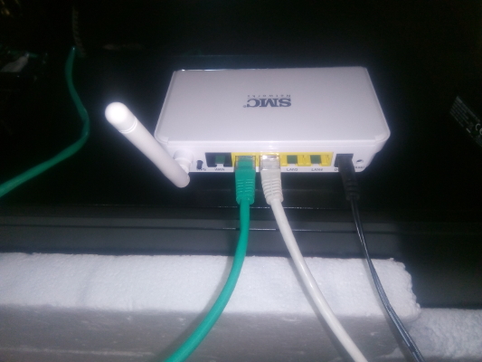
If you want to work on your own machine, use the router SMC to create a ssh connection to the atlas computer.
Step 1: Turn on the SMC router.
Step 2: Plug the ethernet cable from the SMC router to your own computer (white cable on the figure).
Step 3: On a terminal, run (on your computer):
sudo gedit /etc/hosts
this will open the hosts file. You should save the AtlasCar2 network ip (add this to your hosts file):
192.168.2.102 ATLASCAR2
Save and close.
Step 3: Make sure if the connection to atlascar is on, by running
ping ATLASCAR2
Step 4: Get into the atlas environment by running, on a new terminal (the '-X' is for you visualize the image that sensors are capturing):
ssh atlas@ATLASCAR2 -X
Now you are inside the atlascar machine in your own computer!
You can work with Visual Studio or CLion, as they are already installed.
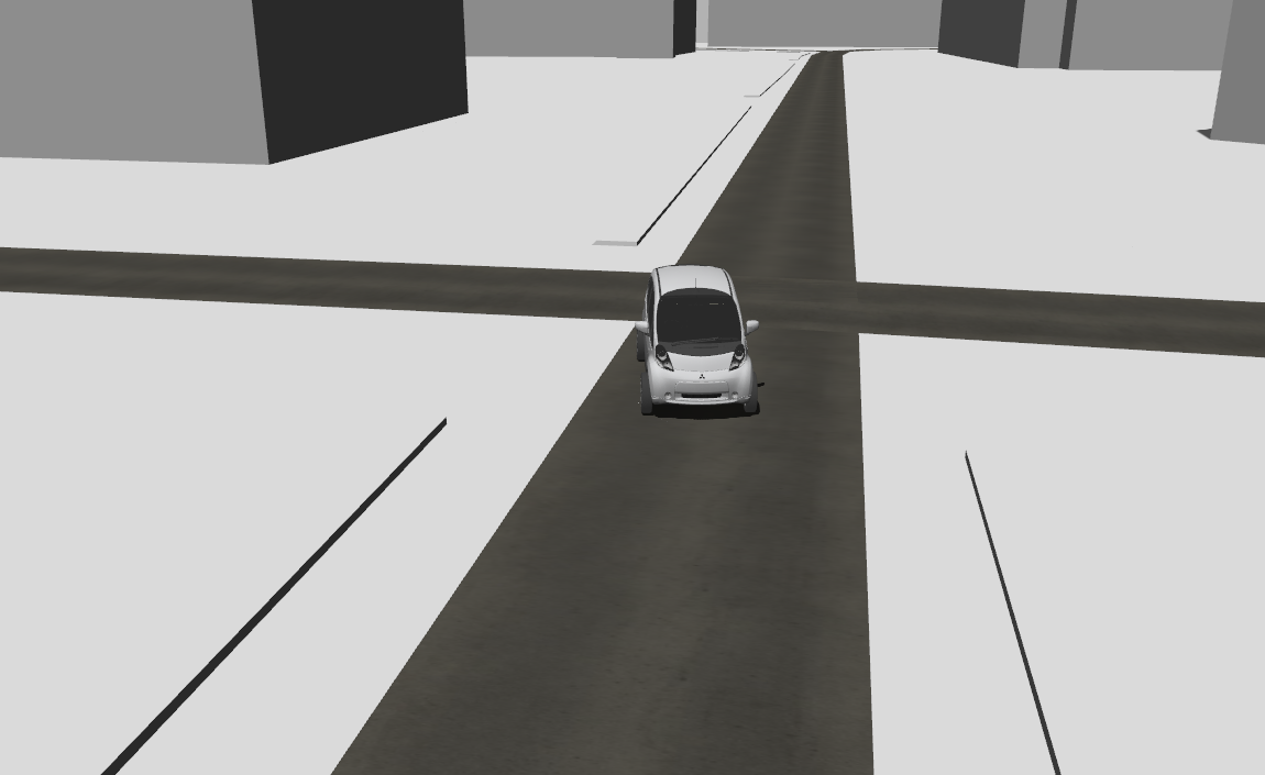
In order to ease the remote work with this vehicle, a simulated environment was developed. This environment uses an ackermann controller that needs to be installed with the following command:
sudo apt-get install ros-noetic-ros-controllers ros-noetic-ackermann-msgs ros-noetic-navigation ros-noetic-pointgrey-camera-description ros-noetic-sick-scan ros-noetic-velodyne-description
The user also needs to download and configure the repository gazebo_models_worlds_collection in order to run AtlasCar2 in Gazebo.
The ATOM repository is also needed.
Lastly, the steer_drive_ros (on the melodic-devel branch) needs to be downloaded in the user's ROS workspace.
Now, to start Gazebo the user writes:
roslaunch atlascar2_gazebo gazebo.launch
And to spawn the car and start the controller the user writes:
roslaunch atlascar2_bringup ackermann_bringup.launch
To control the car, publish a twist message to the /ackermann_steering_controller/cmd_vel topic.
A video example of the simulation can be seen here.
In order to calibrate atlascar2 in the simulated environment, the user needs to run a separate gazebo world:
roslaunch atlascar2_gazebo gazebo_calibration.launch
And a separate bringup:
roslaunch atlascar2_bringup ackermann_bringup.launch yaw:=-1.57 x_pos:=0 y_pos:=2 z_pos:=0 calibration:=true
After that, follow the instructions on the ATOM package.


