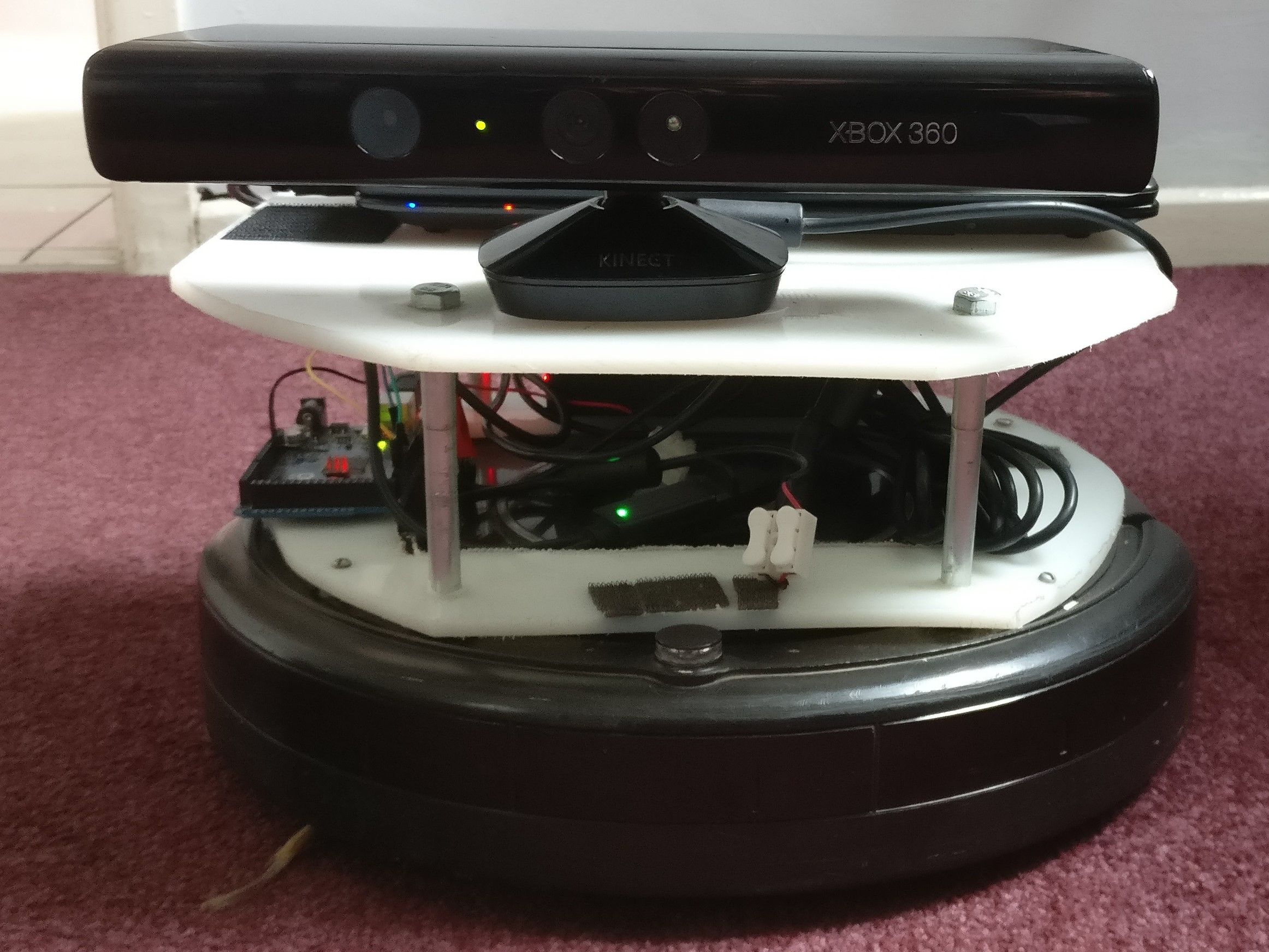
I have been using this base that I built on top of a old Roomba Vacuum cleaner for some time, and have built a number of different robots with it.
My granddaughter named it "Keith", and gives it googly eyes.
Previous instantiations have included a variety of computers used to drive it, including a Netbook Linux computer, a battery-powered Udoo x86, and Raspberry Pis.
I have also attached various sensors and other devices to it, such as a Microsoft Kinect for mapping, robot arms and cameras.
I have used the Robot Operating System (ROS) running the navigation stack and the gmapping SLAM software to map my house.
Here is a version that used the Micosoft Kinect and the Udoo x86 computer.
I have also used it with a camera and TensorFlow software to do object recognition.
The Roomba has a Serial Command Interface that allows software to drive it via a DIN plug. The same plug also provides 15v output from the Roomba's battery.
The Roomba SCI uses 5v TTL logic, so cannot be directly driven from 3.3v logic. In the past I used an Arduino as a relay for the commands with a USB interface for the driver computer.
In this version I decided to use a bi-directional level shifer instead.
I have also used a variety of devices to drive the electronics from the Roomba battery. This latest version uses a DC-DC Converter.
This time, I wanted do two things:
- Experiment with using an FPGA for robotics
- Use a Lidar device for navigation, mapping and obstacle avoidance
Lidar devices are now much cheaper, and are far smaller and much more power-efficient than the Microsoft Kinect.
I deccided to use the LD19 LiDAR sensor from the LDROBOT D300 LiDAR Kit.
I have been doing projects with various open-source Field Programmable Gate Array (FPGA) boards for the last few years.
The board I decided to use for this is the Blackice Mx by @folknology (Al Wood). It is a Lattice ice40 hx4k device, which provides 8k LUTs (see below) when used for the open-source FPGA toolchain. It also has 16kb of BRAM memory and also SDRAM memory, but the SDRAM is not currently used.
 .
.
Field Programmable Gate Arrays are configurable chips. You write code in a Hardware Description Language (HDL) to turn the FPGA chip into, effectively, a custom-chip of your own design. So you are not writing software, but hardware! Lately, to avoid confusion, people have started calling the code you write for FPGAs, "gateware" as it is effectively a set of digital logic circuits built out of logic gates. In fact FPGAs are built out of Lookup tables (LUTs), which are configurable logic elements that contain a multi-input and output configurable logic gate and also flip-flops for storing data. The LUTs are wired together by a set of switches to form the desired logic cicuits. At least one person I know, calls programming FPGAs, "LUT programming". But the HDL you write can also be used, often unchanged, to produce Application-Specific Integrated Circuits (ASICs), i.e real physical custom chips. So FPGA programming is effectively chip design (or at least a major part of it).
So this time I wanted to do as much driving of the Roomba-robot as I could in gateware.
Hardware (or gateware) is much faster and more parallel than software, but is it is not practical to write large applications in hardware. Instead the trick is to define hardware support for your software applications, so that you get the best of both worlds. So I was interested in experimenting with hardware support for mobile robot applications such as navigation, localisation and mapping.
The Hardware Description Language that I decided to use is Amaranth HDL designed and written by @whitequark.
This uses the Python programming language to generate the HDL, which gives it much expressive power. There are two sorts of digital logic used in HDLs, synchronous logic and combinatorial logic. Combinatorial logic is a set of logic circuits with inputs and outputs, but with no memory. So the outputs are continuously driven from the inputs using the logic expressions that you specify. Synchronous logic, by conntrast drives flip-flops or sets of flip-flops called registers, that are updated by the rising or falling edges of a periodic clock signal. Together these allow you to implement any digital logic function that you desire. But they are usually supplemented by memory blocks that hold much more memory than is practical in flip-flops and registers, but in a much less flexible way.
In amaranth there is a "domain" for combinatorial logic, called "comb", and one or more domains for synchronous logic each with its own clock. Simple designs use just one clock and there is a default clock domain called "sync".
Amaranth code is divided into a set of modules. Inputs, outputs and registers are all specified as signals with a width in bits and other properties.
To generate a combinatorial statement you write:
m.d.comb += a.eq(b)
This adds a the statement a.eq(b) to the set of cominatorial statements for the current module, and sets signal a to the value of signal b.
Similarly to set a register x, to a signal y on the rising edge of the default clock, you write:
m.d.sync += x.eq(y)
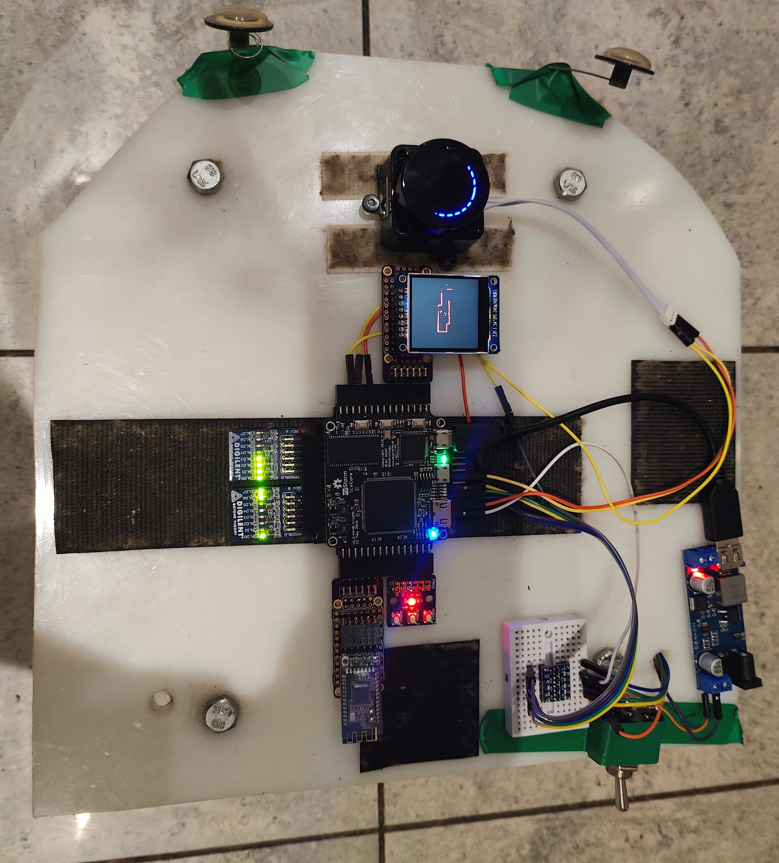
A rough schematic of the electronics used by the FPGA Roomba robot is:
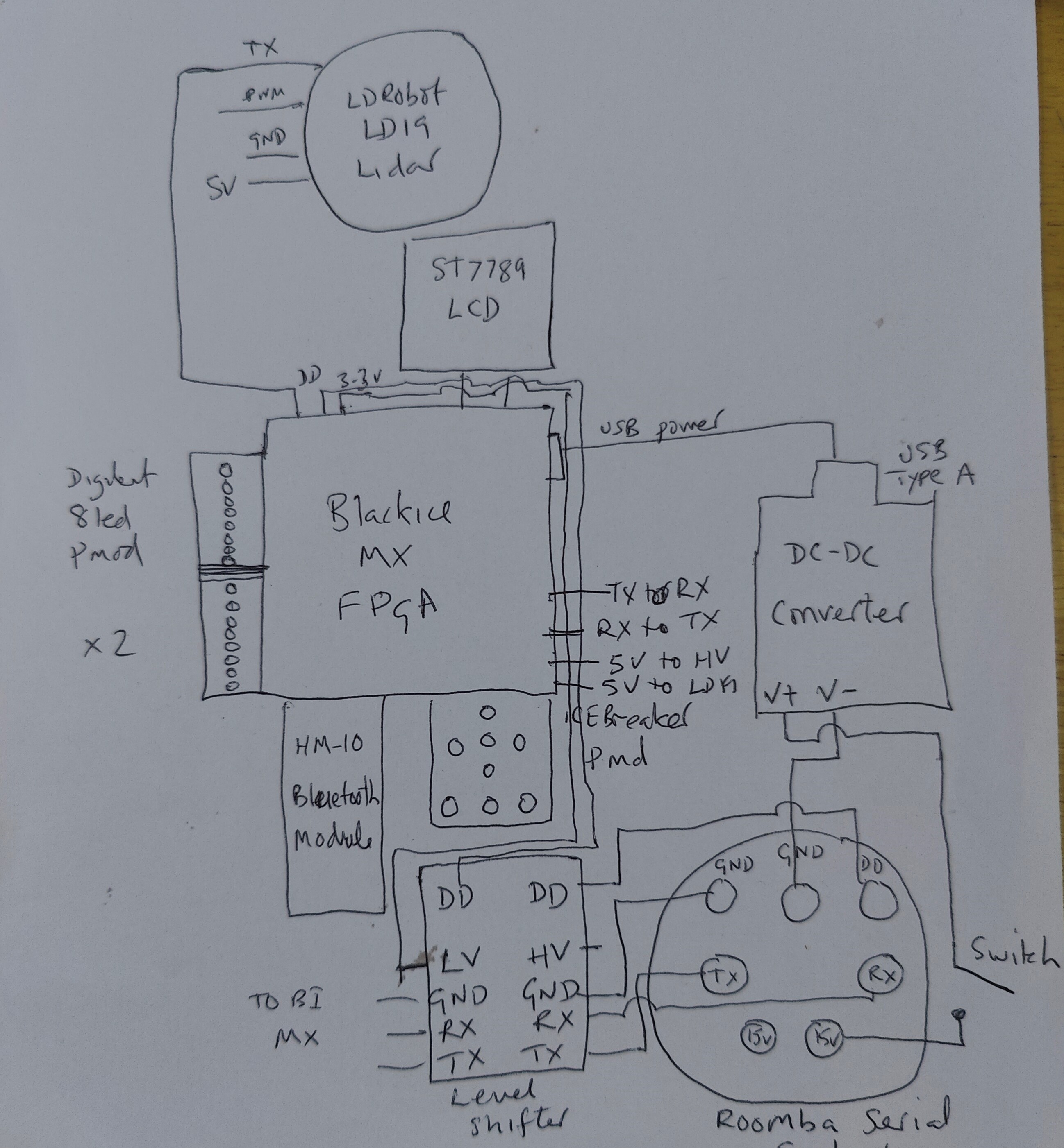
The 15v signal from the Roomba goes, through a switch, to the DC-DC converter which has a USB type A socket, which is used to power the FPGA.
The DD, TX and RX signals from the Roomba DIN socket go to the level-shifter that converts them to 3.3v logic. They then go to TX, RX and DD FPGA pins.
The HM-10 Bluetooth module is connected via a handmade Pmod to the FPGA It uses another uart interface.
The Lidar takes 5v power from the FPGA, and its uart TX signal which sends the lidar data is connected to another pin on the FPGA.
Two Digilent 8Led Pmods are used to display a 16-bit value in binary for diagnostic purposes. It can be used to show the distance to an obstacle at the front off the robot.
There is also at ST7789 240x1240 pixel 16-bit colour LCD screen attached to the FPGA by another homemade Pmod.
This is used to display a 2D grid-occupancy map of the robot's environment.
There is also an iCEBreaker Pmod that gives 3 more buttons for control functions, and 5 led for diagnostic functions, to supplement the 2 buttons and 2 leds that the Blackice Mx FPGA provides.
There is no software used in this project, just this Amaranth gateware.
Although an Arduino Bluetooth Controller can be used to control the robot and that obviously uses software. (Although an FPGA remote control would be quite easy to produce, which would eliminate that use of software).
The main parts of the gateware are:
- Memory to hold pre-caculated sin and cosine tables for 450 angles from 0 to 360 in 0.8 degree increment. This is what the LD19 lidar device sends for each rotation.
- Memory to hold the occupancy grid map, displayed on the LCD
- Button debouncer HDL modules for button control
- Use of the aramarhth-stdio uart HDL for each uart
- An HDL driver module to the ST7789 LCD
- A state machine for waking up the Roomba and defining commands to send to it
- A memory ROM with pre-defined commands to send to the Roomba
- A song definition for a song for the Roomba to play using midi notes
- A state machine to send the commands to the Roomba via its uart
- A state machine to read sensor data from the Roomba
- A state machine to read in and execute single-character Bluetooth commnds, such as forwards, spin left and stop
- A state machine to read the Lidar data and create the map from it
- A circuit to detect and object in front of the robot and stop it
Here is a video of an early version of the robot being driven by the Phone App, and stopping when an obstacle (my foot) is detected.
If the data from this robot is send to a host computer, e.g, a Raspberry Pi, then a fast SLAM algorithm can be applied to the data.
I am currently trying to convert this SLAM-2D-LIDAR-SCAN python project to use the lidar data from the LD19 sensor.
That project implements an OccupancyGrid class that draws an Occupancy Grid Map from the Lidar data. This is an example using the LD19 sensor:
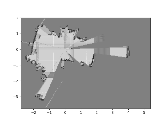
There is then a ScanMatcher_OGBased class that takes an existing occupancy grid and uses the Lidar data to locate the robot within the map.
And finally there is a FastSLAM class that uses those two classes to implement the Dast SLAM algorithm using a particle filter.
I am planning to send the roomba sensor data to the host and calculate the robot pose from it. That, plus the lidar range data and timestamps is what the Fast SLAM algorithm requires.