WARNING: information distributed in the hope that it will be useful, but without any warranty.
Copyright (C) Cosmin Gorgovan 2014. This work is licensed under a Creative Commons Attribution-ShareAlike 4.0 International License.
Hubsan H107 is a series of low cost ready-to-fly micro quadcopters. There are 4 models:
- H107 - the base model, uses 7x20 mm coreless brushed motors and 240 mAh LiPo cells
- H107L - adds an upwards pointing LED on each arm
- H107C - adds a camera which can record to a micro-SD card and upgrades to 8x20mm coreless brushed motors and 380 mAh LiPo cells
- H107D - is similar to H107C but it removes the micro-SD card and adds a video transmitter for First Person View (FPV) flying
When I've started I was just looking for a micro-sized low cost hardware platform with widely available spare parts for which to write my own flight controller software. In the meantime, I've realised there are at least two possible applications which might be of interest to the general RC community:
-
repurposing the tiny (3 x 2 cm) low cost ($10-$15) controller board which contains a Nuvoton MINI54 (Cortex-M0 based) microcontroller, a 3 axis gyroscope, a 3 axis accelerometer, an A7105 wireless transceiver and 4 power MOSFETS capable of driving brushed motors
-
writing custom software to improve or extend functionality of the H107 (for example to make it work with other radio transmitters that use A7105 (e.g. flysky), to enable flying in acrobatic mode, to increase pitch and roll rates)
-
I've mostly looked at the plain H107 model. H107L is very similar and I expect everything to apply to it as well. I have no plans regarding H107C and I haven't looked at H107D yet, but both seem reasonably similar to the base model. H107D is on my TODO list, there's some interest in using its FPV module on other platforms.
-
I've identified and found documentation for all ICs
-
I've traced all the connections and PCB traces required to develope a feature-equivalent firmware from scratch
-
I'm publishing high quality photos of the PCB which should be sufficient to verify and/or extend my analysis
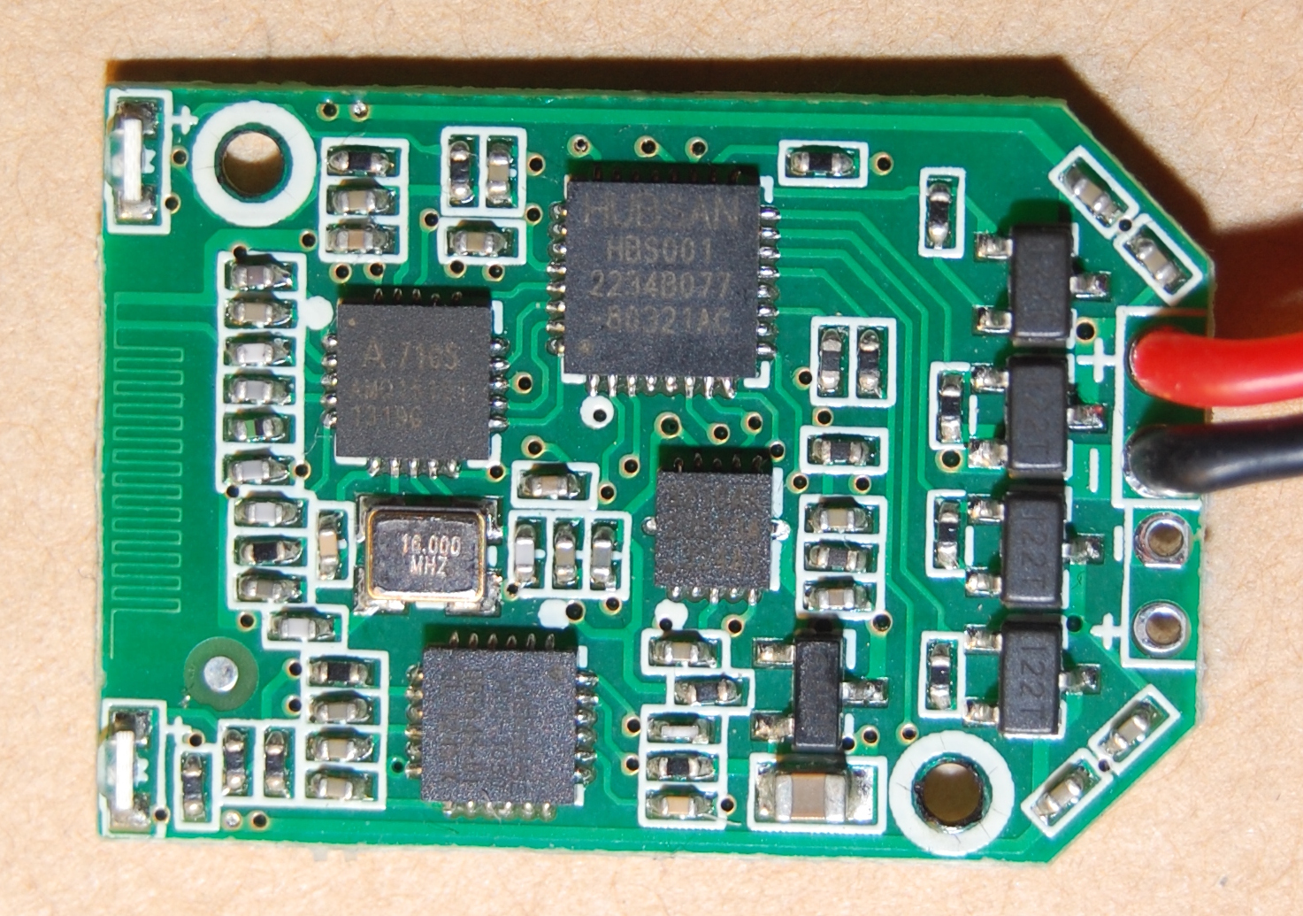
Below is a picture of the H107 PCB top (left side of the picture is mounted at the front of the quad):
![H107 PCB top] (https://raw.githubusercontent.com/lgeek/h107_rev/master/img/h107/pcb_top_overview.jpg)
From left to right, we have:
- the two blue LEDs which look like eyes, with the antenna between them
- Amicom A7105 Transceiver covered by the crystal in cylindrical package - replaced with an SMD crystal in later revisions
- below the A7105 and slightly to the right: Invensense MPU-3050 3 axis gyroscope
- middle, top, the largest package: Nuvoton MINI54ZAN MCU - marked HUBSAN HBS001 in later revisions
- below and slightly to the right of the MINI54 MCU: mCube MC3220 3 axis accelerometer - later replaced with MC3210 - it was a real PITA to identify
- below and to the right of the M3220: Torex XC6206 3V LDO regulator
- 4 identical devices aligned vertically and marked 122W: unknown N-Channel power MOSFETs
- battery power input
There's nothing particularly interesting about the passives.
All ICs are orientated according to the silkscreen marking, the white circle shows pin 1.
For comparison, below are an overview of the H107L PCB and a macro showing the IC markings much more clearly.
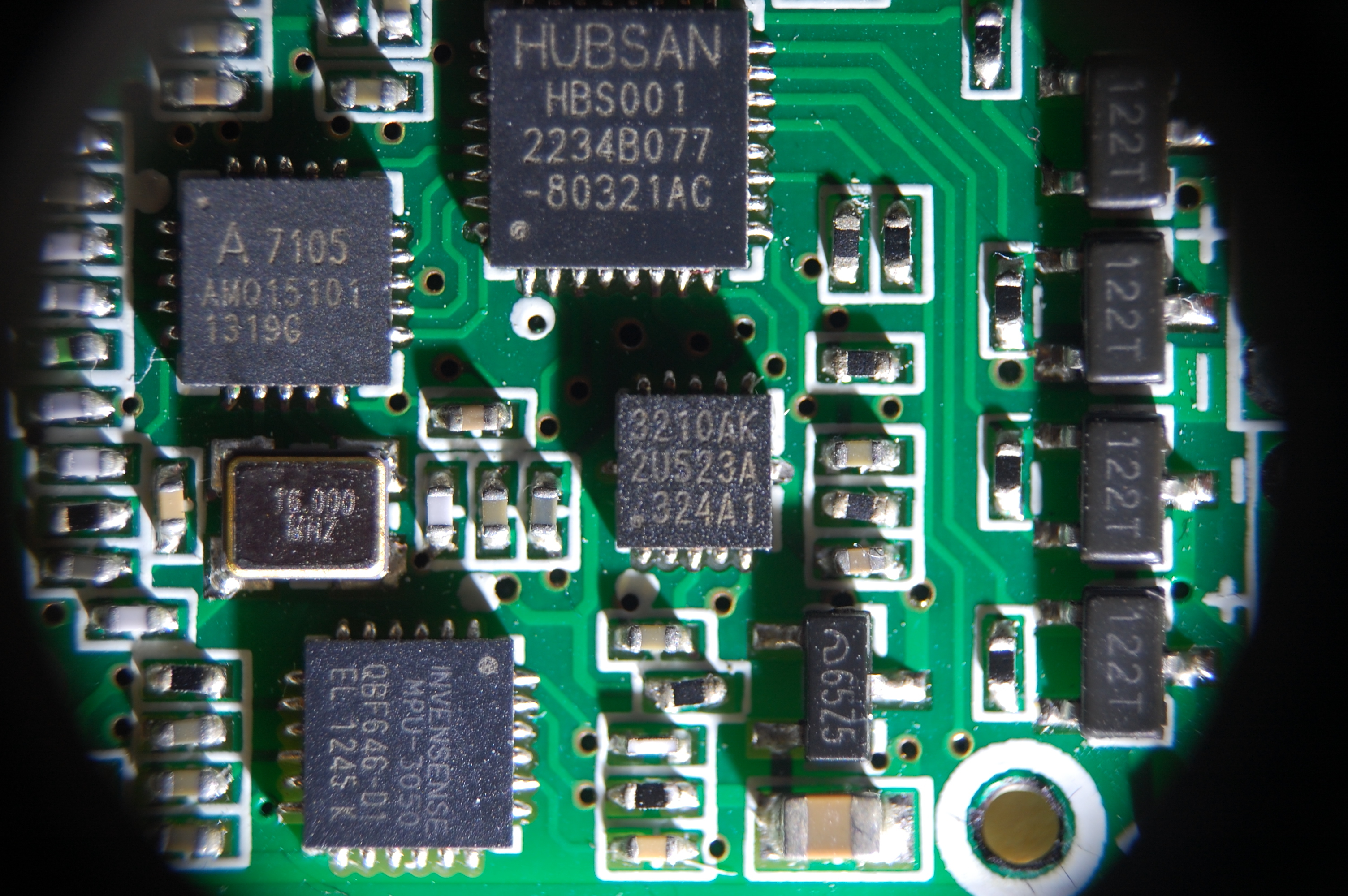
- Amicom A7105 Transceiver
- MPU-3050 Gyroscope, MPU-3050 register map
- MINI54ZAN TRM MCU
- The MC3220 accelerometer doesn't seem to officially exist, but as far as I can tell it's a MC3210 in a package pin-compatible with Bosch BMA180
- XC6206 voltage regulator
- RTC6705 video transmitter
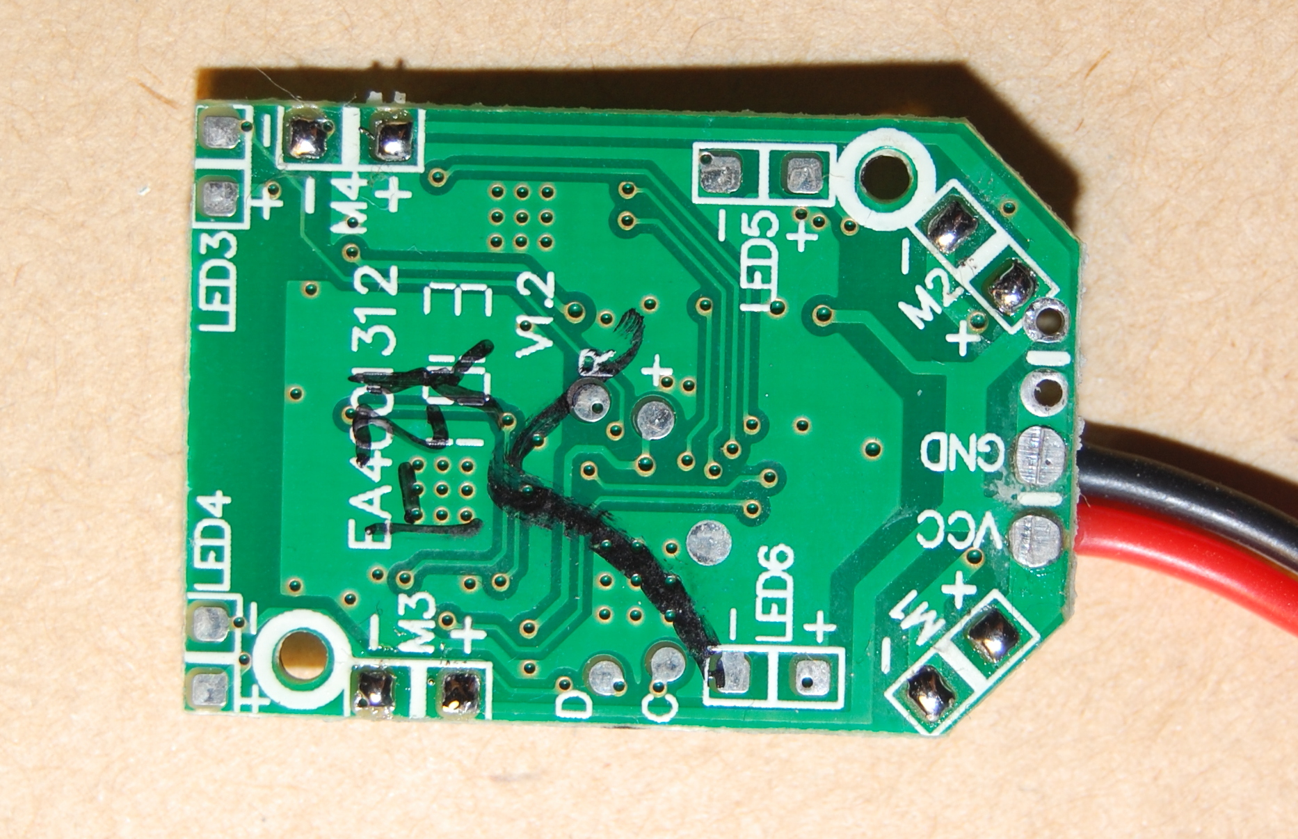
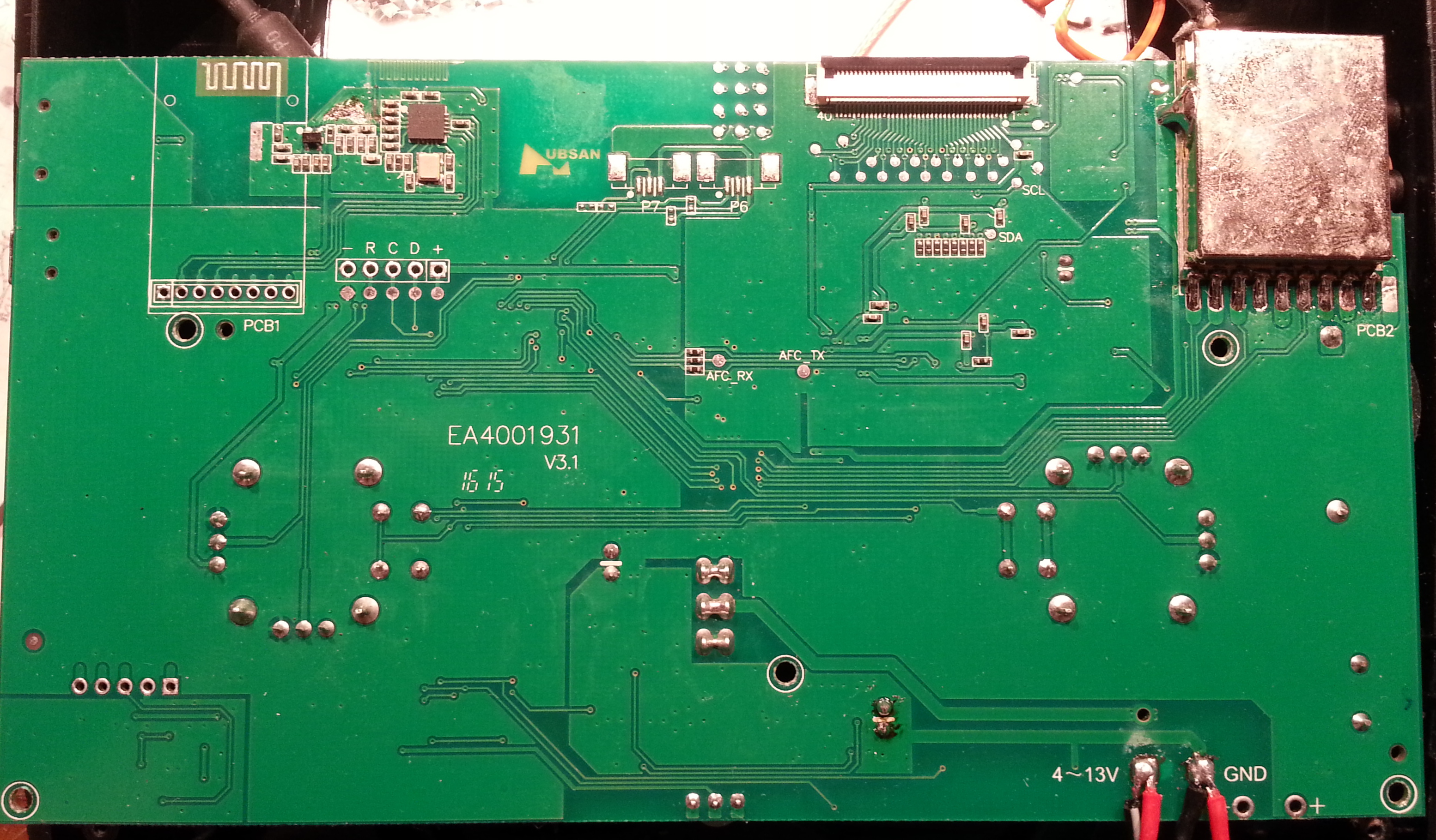
The picture below shows the goodies on the bottom side of H107L: the D and C pins are SWDIO and SWCLK respectively! The pad marked R is reset. H107 includes the same pads in more or less the same position, although the rest of the bottom layout is slightly different.
MINI54ZAN:
1 - voltage divider (10K from GND and 10K from VBAT) - used to detect battery voltage
2 - reset pad
3 - LED3-
4 - NC
5 - NC
6 - MC32x0 INT
7 - I2C SDA (MC32x0, MPU-3050)
8 - I2C SCL (MC32x0, MPU-3050)
9 - MPU-3050 INT
10 - NC
11 - H107: NC, H107L: A7105 CKO
12 - GND
13 - H107: unpopulated pad, H107L: LED5+
14 - MOSFET gate for motor front, left
15 - MOSFET gate for motor back, left
16 - MOSFET gate for motor back, right
17 - MOSFET gate for motor front, right
18 - H107: NC, H107L, LED6+
19 - SWDCLK
20 - SWDIO
21 - NC
22 - NC
23 - NC
24 - LED4-
25 - NC
26 - NC
27 - H107: VREG, H107L: NC
28 - VREG
29 - A7105 GIO1
30 - A7105 SDIO
31 - A7105 SCK
32 - A7105 SCS
The two LEDs on the PCB are connected in parallel with LED3 and LED4 respectively.
The MCU is read and write protected, so the firmware image can't be directly read out. Glitching - it's clocked by IRC :( - or a software vulnerability might allow bypassing the protection, but I'm not sure it's worth the time.
The MCU can be unlocked (which also erases the firmware) using NU-LINK and Nuvoton's proprietary software. It would be useful to reverse engineer the unlocking procedure in order to drop the requirement for this programmer.