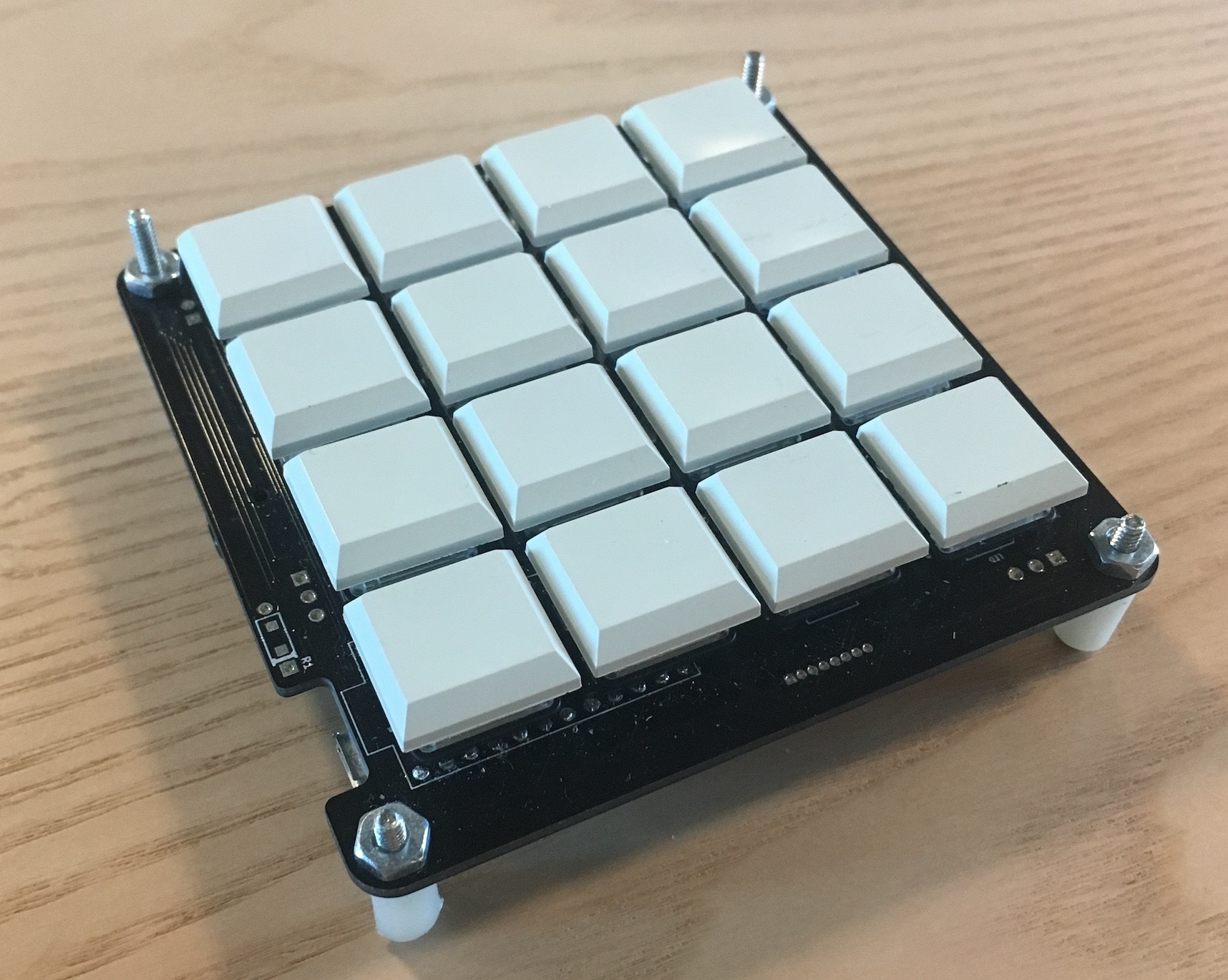
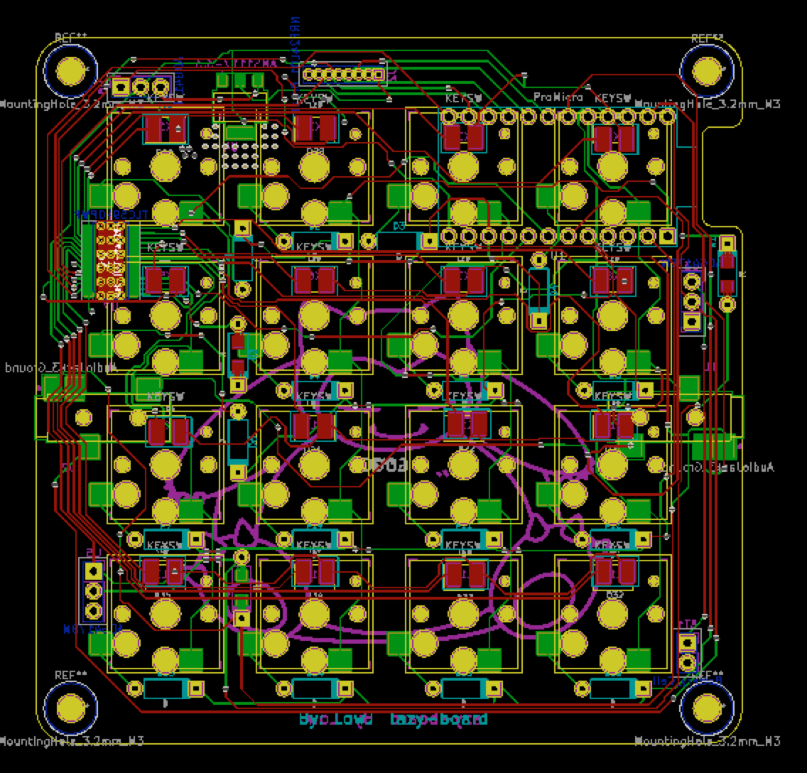
https://texasinstruments.hackster.io/jwlow/multipurpose-keypad-682653
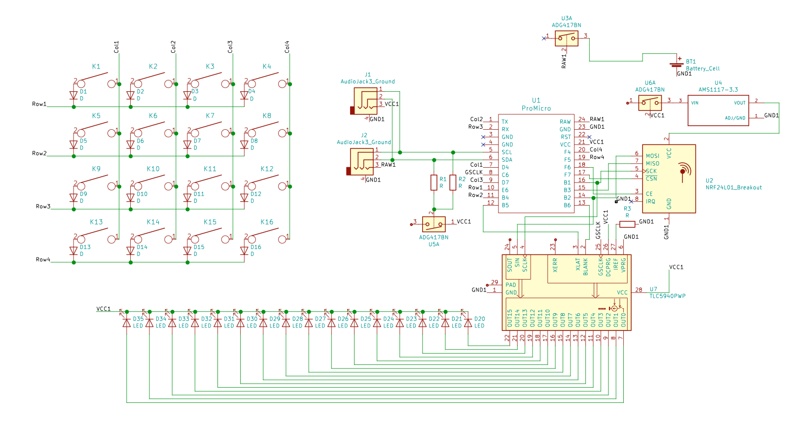
If you want to build one of these yourself, follow this guide.Here is a list of parts you will need.
- Pro Micro - An arduino programmable board.
- TI TLC5940 - LED Driver used to control the 16 LEDs.
- Schottky diode(16) - Used to prevent unwanted key presses (keyboard ghosting).
- Kailh Choc switches(16) - The type of mechanical switch used for each key. There are many types avaliable which feel and sound different (clicky, tactile, linear)
- Kailh Choc PCB sockets(16) - Sockets for the Choc Switches soldered on to the PCB. Sockets allow for the mechanical switches to be taken out easily.
- Kailh low profile keycaps(16) - Keycaps for the mechanical switches.
- 3528 SMD LEDs(16) - The PCB has pads for SMD LEDs, I made the pads large so different kinds of sizes would work.
- 10K Resistor - For the LED driver.
- Solder Wick - Needed for hand soldering the LED driver.
- PCBs can be obtained by ordering them through sites like JLCPCB or PCBway. Ive ordered PCBs from both of them, the prices are good. One of the draw backs is that shipping to the US can talke 3-4 weeks.
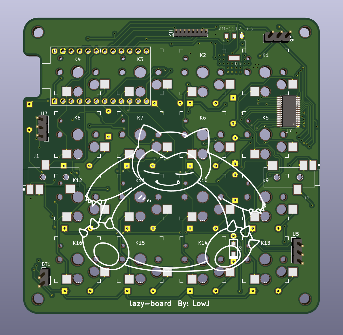
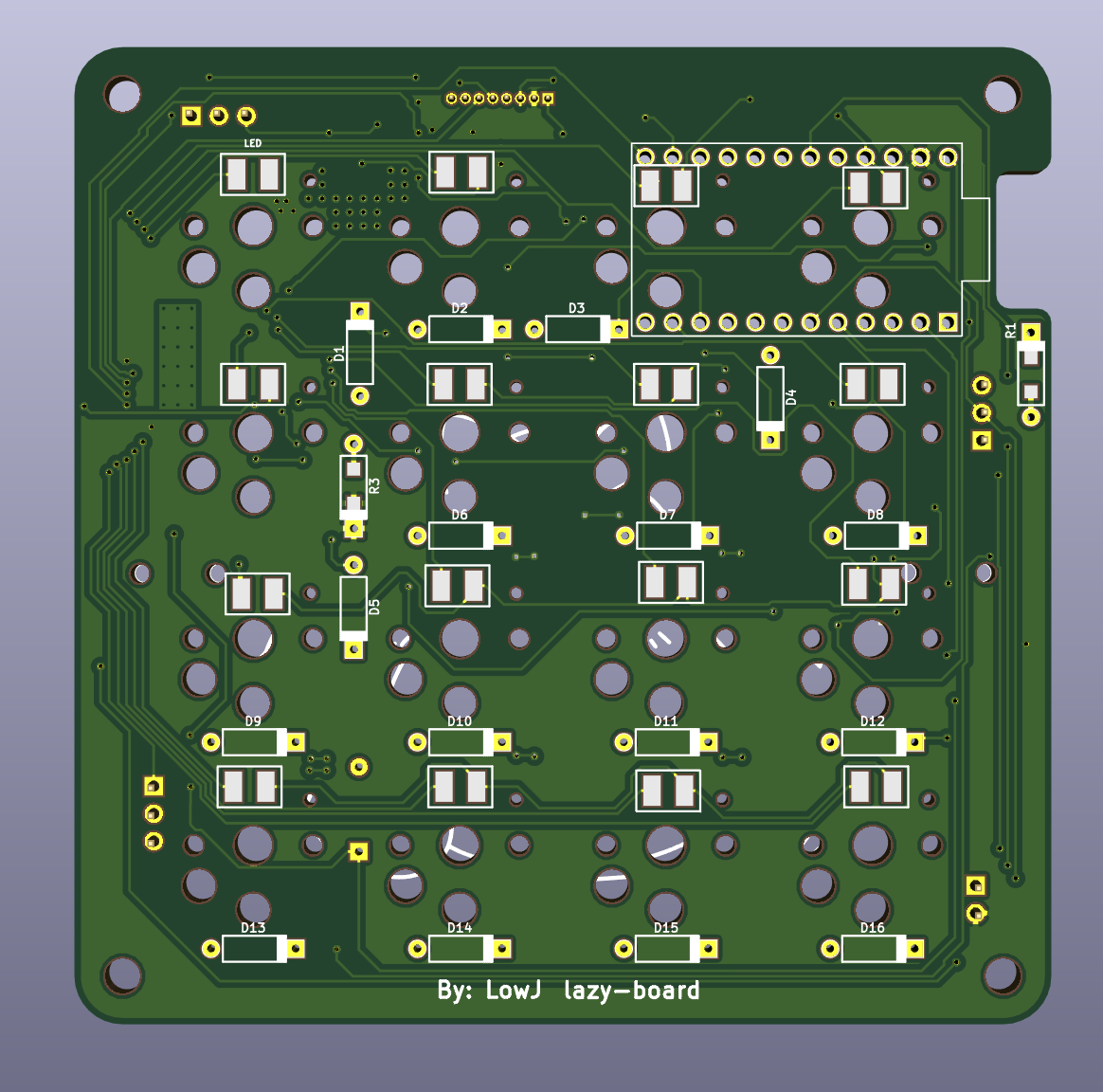
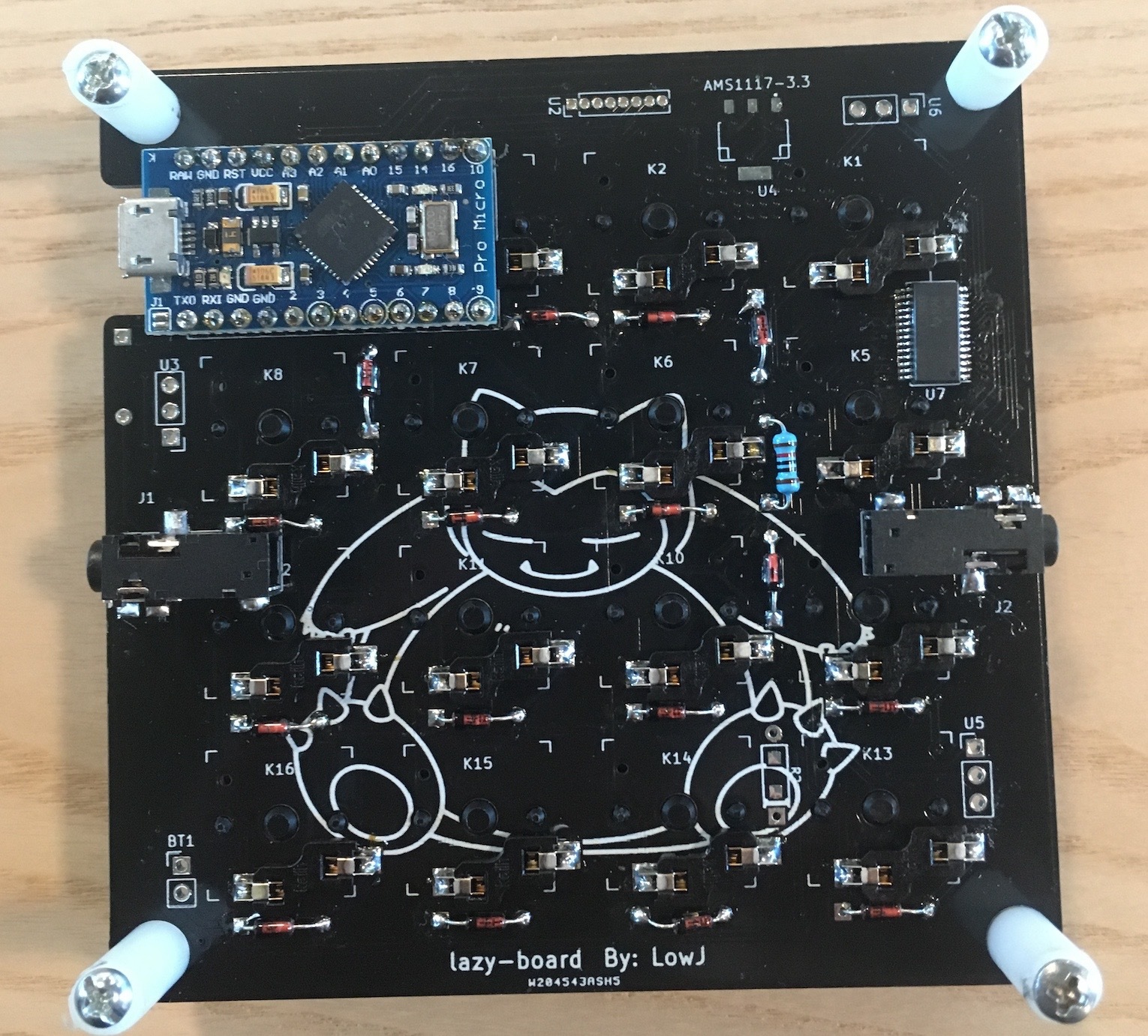
- I will use the terms front and back. Back will refer to the side with the Snorlax.
- If you look at the led pad in the top left, it labels the positive and negative. The rest of the LEDs will follow this orientation. When soldering the LEDs on, start just by soldering it on to one of the pads, this will make it easier to adjust. Then check if it is positioned correctly by trying to place the switch in. Adjust if needed. Once each LED is aligned properly solder in all the other ends.
- First align the driver with the solder pads, it helps to solder in one of the ends to keep it in place. Next place a bunch of solder on all the pins so everything is connecting. Then take some wick and place it in a group of 4-8 pins to remove the solder. This should remove the solder between each pin, however the solder connecting the pad and the pin will stay. Repeat this with the rest. (PIC)
- Make sure you solder the 10K resistor (R3). Make sure it is installed on the back side.
- When putting in the diode, the direction matters. Follow the labeling on the front side. Also make sure to install the diodes on the back side of the pcb, this will allow for the housing to fit properly. Cut the excess leads.
- First install all the sockets. Sockets at K3 and K4 will need to have the bottom portions cut with an x-acto to allow for the pro micro to fit in. Once the pro micro is installed, cut the excess leads. Try to make sure the cuts are as close to the board as possible, as a switch will be installed on top of them. (PIC)
- I included the dxf files for the housing I used in the laser cutter. It uses #2 screws to hold everything together.
- Key presses can be modified by changing the key array in line 14. If you want to use keyboard modifiers, refer here https://www.arduino.cc/en/Reference/KeyboardModifiers.
- There are 3 preset lighting modes and the three left most keys in the bottom row will cycle between them. I will figure out a way to be able to unbind them...
