- Sangjun Son (2020/02/27)
- Modeled testbed included server room equipped with two heterogeneously occupied racks (with each server modeled separately) and one roof-mounted cooling device.
- Setup was examined virtually for 3 servers power usage scenarios and also 3 air conditioning temperature scenarios.
- Each rack has 8 and 6 active devices respectively.
- The dataset is every second measurement of temperature in 4 virtual probes, inlet/outlet of each server and air conditioner.
- Detailed numerics of the server room can be found in link mentioned above.
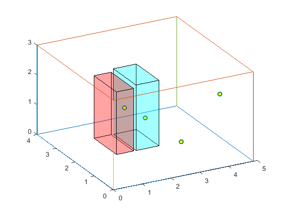
- Brief diagram of server room (red: rack 1, blue: rack 2, dots: virtual probes)

- # of 1st scenarios (air conditioning temperature setup) : 3
- # of 2nd scenarios (power usage variation) : 3
- # of temperature probes : 34
- # of measuring time (every 1s) : 4157
- ServerRoomCFD.tensor: 4
- Mode 1 : air conditioning temperature setups (24, 27 and 30 Celsius degrees)
- Mode 2 : power usage (50%/75%/100% scenario)
- Mode 3 : temperature probes
- Mode 4 : duration time (3000~4000s)
| Index of <Probe> | Probe Location |
|---|---|
| 1~2 | Inlet/Outlet of air conditioner |
| 3~6 | Virtual probe located in (1.8, 2.12, 1.42), (4.8, 1.65, 1.5), (2.5, 2.09, 0.95), (2.8, 0.65, 0.75) (in the same order as the website) |
| 7~22 | Inlet/Outlet surfaces (odd/even indices) of each server in rack 1 |
| 23~34 | Inlet/Outlet surfaces (odd/even indices) of each server in rack 2 |
- ServerRoomCFD.tensor : <AirCon> <Power> <Probe> <Time> (Temperature)
- Temperatures are in absolute degrees.
- ServerRoomCFD.tensor : 3 * 3 * 34 * 4,157
- ServerRoomCFD.tensor : 1,009,426 (79.4%)
- Length of time mode varies from scenario to scenario.