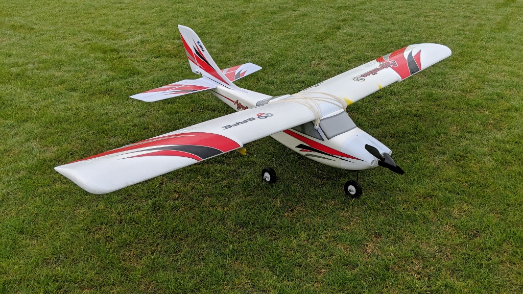
This repository hosts code used in a flight data collection system developed for a radio-controlled aircraft. This includes code used to collect data, as well as code used to process, filter, and visualize the data. Click here for more details about the project.
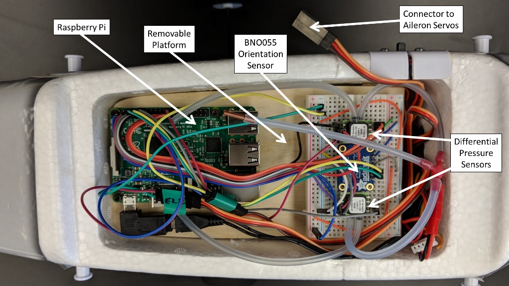
A Raspberry Pi 2 is used as an onboard computer. The aircraft's roll, pitch, and heading are measured with an Adafruit BNO055 orientation sensor. Airspeed and angle of attack are measured by a system of two pitot-static tubes connected to differential pressure sensors. One pitot-static tube is mounted under the right wing facing toward the front of the aircraft, while the other is mounted under the left wing and is tilted downward at an 80 degree angle. Elevator deflection and throttle setting are measured by connecting the PWM outputs of aircraft's radio receiver to GPIO pins on the Pi. Using interrupts, the rising and falling edges of the PWM signal are recorded so that the PWM signal can be reconstructed. Descriptions and derivations of the calibration functions used to convert raw data into final values can be found in the project writeup.
Data collection code is written in C and is used by the Raspberry Pi 2
to interact with sensors and log data. Python code for processing the collected data and
creating plots uses pandas to read in and manipulate data, scipy to filter noise
and perform numerical root finding, and matplotlib to generate plots. The files in
the repository include:
collection/main.c- Initialize and calibrate sensors, setup interrupts, poll orientation sensor, and write data to CSV files.
collection/FlightSensors.candcollection/FlightSensors.h- Contains functions and interrupt service routines used to communicate with sensors.
Three separate Python scripts located in the processing folder read in data, process it as
necessary, and generate plots. Sample data is also included in this folder so that the
scripts may be run.
processing/AirspeedAndAOA.py- Smooth out noise in the differential pressure data using a Savitzky-Golay filter.
- Compute airspeed and angle of attack from calibration functions.
- Generate plots of Airspeed vs. Time and Angle of Attack vs. Time.
processing/Orientation.py- Correct pitch angle.
- Generate plots of Roll vs. Time, Pitch vs. Time, and Heading vs. Time.
processing/Controls.py- Compute the "ON TIME" of the PWM signal from rising edge and falling edge times.
- Smooth out noise in "ON TIME" using a Savitzky-Golay filter.
- Compute elevator deflection angle and static thrust from PWM "ON TIME."
- Generate plots of Elevator Deflection vs. Time and Static Thrust vs. Time.
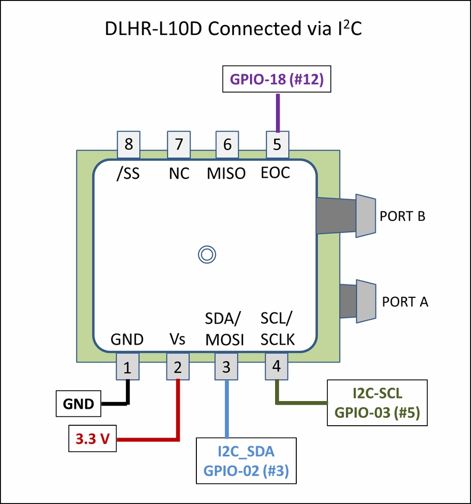
The data collection code assumes that the sensors are connected to the Raspberry Pi 2 pins as follows:
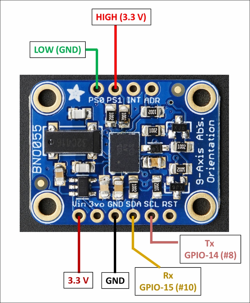
- Use 3.3 V for power.
- Must set
PS0pin toLOWandPS1pin toHIGHon the BNO055 to select UART mode. - In UART Mode the
SDApin becomes the transmitTxpin and theSCLpin becomes the receiveRxpin. - Connect the
Tx(SDA) pin on the sensor to theRxpin on the Raspberry Pi 2 and connect theRx(SCL) pin on the sensor to theTxpin on the Raspberry Pi 2.
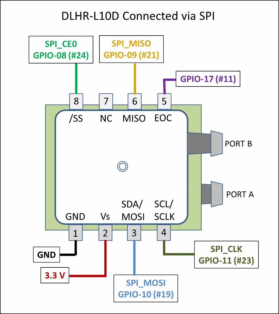
- SPI
- Use 3.3 V for power.
- While there is only one SPI bus on the Raspberry Pi 2, there are two chip enable
pins
SPI_CE0andSPI_CE1. Connect the pressure sensor'sSSpin to the Raspberry Pi'sSPI_CE0pin (GPIO-08, #24). - Connect the pressure sensor's
EOCinterrupt pin to GPIO-17 (#11) on the Raspberry Pi. - Connect the remainder of the SPI pins (MISO, MOSI, SCLK) to their corresponding pins on the Pi.
- I2C
- Use 3.3 V for power.
- Connect the pressure sensor's
EOCinterrupt pin to GPIO-18 (#12) on the Raspberry Pi 2. - Connect the remainder of the I2C pins (SDA, SCL) to their corresponding pins on the Pi.
For each channel, the aircraft radio receiver has three pins: ground, power, and PWM signal. Only the ground and PWM signal pins should be connected to the Raspberry Pi 2. DO NOT connect the power pins to the Pi. The PWM signals are treated as an interrupts and are connected as follows.
- Elevator PWM signal from receiver connected to GPIO-27 (#13).
- Throttle PWM signal from receiver connected to GPIO-22 (#15).
- Remember to connect the
GNDfor each receiver channel to theGNDof the Pi.
The data collection code uses the WiringPi library. WiringPi is now pre-installed on standard Raspbian systems. The pin numbers referenced in the code are WiringPi pin numbers, not the standard Raspberry Pi 2 pin numbers.
- Follow the directions here to make sure WiringPi is pre-installed. If not, follow directions to download and install.
- In the
collectionfolder, compilemain.c, making sure to link the wiringPi library. For example:
gcc -Wall main.c -lwiringPi
- Make sure the aircraft is on a level surface and execute the code:
./a.out - Each time the data collection code is run, the sensors (accelerometer, gyro, magnetometer) on the
BNO055 orientation sensor must be calibrated. This process begins automatically when the code is run,
and you should see continuously updated messages on the screen such as "MAGNETOMETER not fully
calibrated" and "ACCELEROMETER not fully calibrated." The user must put the aircraft in various
orientations to assist in completing the calibration process. Repeat the following steps
until the calibration is complete.
- Leave the aircraft still on a level surface for several seconds.
- Orient the aircraft such that the nose points forward and the right wing points downward and hold still for 3 to 4 seconds.
- Orient the aircraft such that the nose points forward and the top of the aircraft points downward and hold still for 3 to 4 seconds.
- Orient the aircraft such that the nose points forward and the left wing points downward and hold still for 3 to 4 seconds.
- Orient the aircraft such that the nose points upward and hold for 3 to 4 seconds.
- Orient the aircraft such that the nose points downward and hold for 3 to 4 seconds.
- Repeat these steps until the calibration is complete.
- When the calibration is complete, you should see the message "Successful calibration of all BNO055 Orientation Sensor components." The code will then begin collecting measurements.
The output of the data collection code is the following set of CSV files:
dp1data.csvcontains two columns:time(s)anddP1(Pa). dP1 is the differential pressure in Pascals (Pa) recorded by the pressure sensor connected via SPI.dp2data.csvcontains two columns:time(s)anddP2(Pa). dP2 is the differential pressure in Pascals (Pa) recorded by the pressure sensor connected via I2C.imudata.csvcontains four columns:time(s),heading(deg),roll(deg), andpitch(deg). Heading corresponds to the magnetic compass heading in degrees (0/360 North, 90 East, 180 South, 270 West). A right bank is a positive roll, and a left bank is a negative roll. Because of the way the BNO055 was installed, zero pitch is recorded as 180 degrees. The Python data processing code corrects for this.elevatordata.csvcontains one column,time(s). The times recorded are for both the rising edge and falling edge of the PWM signal sent to the elevator servo.throttledata.csvcontains one column,time(s). The times recorded are for both the rising edge and falling edge of the PWM signal sent to the electronic speed controller.spierrors.csvcontains three columns:time(s),read_error,request_error. The two error columns will contain 0 if there was no error, and 1 if an error occurred.i2cerrors.csvcontains three columns:time(s),read_error,request_error. The two error columns will contain 0 if there was no error, and 1 if an error occurred.uarterrors.csvcontains one column,error_msg. Error codes collected in the UART error log are written as text messages.
The following sample data files are included in the processing folder:
processing/sample_data/imudata.csv: from a test flightprocessing/sample_data/elevatordata.csv: from a test flightprocessing/sample_data/throttledata.csv: from a test flightprocessing/sample_data/flight_data/dp1data.csv: from a test flightprocessing/sample_data/flight_data/dp2data.csv: from a test flightprocessing/sample_data/background/dp1data.csv: background readings taken indoorsprocessing/sample_data/background/dp2data.csv: background readings taken indoors
Background differential pressure sensor data was taken by running the data collection code while
the aircraft was indoors to ensure that there would be no airflow over the pitot-static tubes.
AirspeedAndAOA.py averages the background values and subtracts the average background from
the pressure data taken while in flight. All three Python scripts can be run from within the
processing folder.
python AirspeedAndAOA.py
python Orientation.py
python Controls.py
A few sample plots are given below.
