A lab report by Ananya Paul.
Include your responses to the bold questions on your own fork of this lab report template. Include snippets of code that explain what you did. Deliverables are due next Tuesday. Post your lab reports as README.md pages on your GitHub, and post a link to that on your main class hub page.
For this lab, we will be experimenting with a variety of sensors, sending the data to the Arduino serial monitor, writing data to the EEPROM of the Arduino, and then playing the data back.
a. Based on the readings from the serial monitor, what is the range of the analog values being read?
0 to 1023
b. How many bits of resolution does the analog to digital converter (ADC) on the Arduino have?
10 bits, 2^10
How might you use this with only the parts in your kit? Show us your solution.

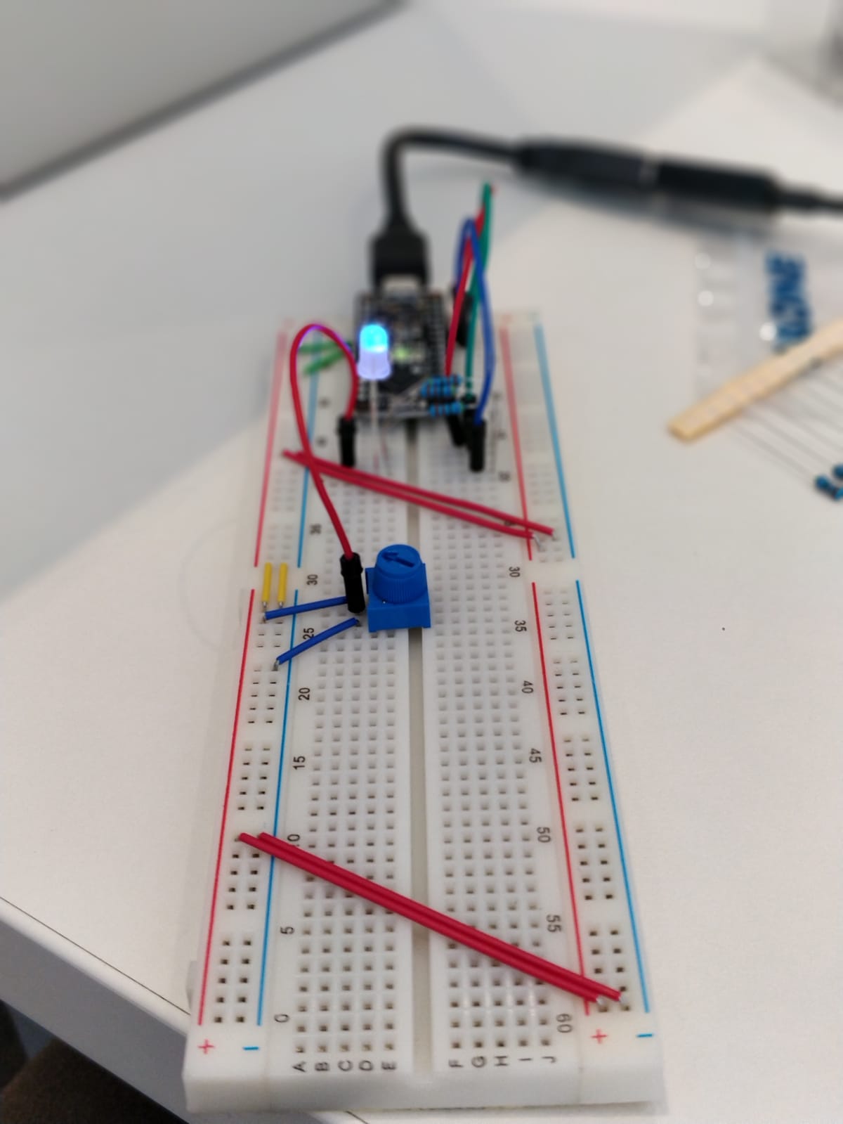
I used the Ohm resistors in the kit.
a. What voltage values do you see from your force sensor? From 0 to 1023
b. What kind of relationship does the voltage have as a function of the force applied? (e.g., linear?)
FSR and Softpot are Logorithmic. Flex Sensor and PhotoCell are linear.
c. Can you change the LED fading code values so that you get the full range of output voltages from the LED when using your FSR?
Connected the common node of the anode to A0, where the voltage is controlled by the pressure resistor.
d. What resistance do you need to have in series to get a reasonable range of voltages from each sensor?
e. What kind of relationship does the resistance have as a function of stimulus? (e.g., linear?) FSR and Flex Sensor are Logorithmic. Photo Cell and Softspot are Linear.
a. Include your accelerometer read-out code in your write-up.
// Basic demo for accelerometer readings from Adafruit LIS3DH

#include <Wire.h>
#include <SPI.h>
#include <Adafruit_LIS3DH.h>
#include <Adafruit_Sensor.h>

// Used for software SPI
#define LIS3DH_CLK 13
#define LIS3DH_MISO 12
#define LIS3DH_MOSI 11
// Used for hardware & software SPI
#define LIS3DH_CS 10

// software SPI
//Adafruit_LIS3DH lis = Adafruit_LIS3DH(LIS3DH_CS, LIS3DH_MOSI, LIS3DH_MISO, LIS3DH_CLK);
// hardware SPI
//Adafruit_LIS3DH lis = Adafruit_LIS3DH(LIS3DH_CS);
// I2C
Adafruit_LIS3DH lis = Adafruit_LIS3DH();

void setup(void) {

#ifndef ESP8266
  while (!Serial);     // will pause Zero, Leonardo, etc until serial console opens
#endif

  Serial.begin(9600);
  Serial.println("LIS3DH test!");

  if (! lis.begin(0x18)) {   // change this to 0x19 for alternative i2c address
    Serial.println("Couldnt start");
    while (1);
  }
  Serial.println("LIS3DH found!");

  lis.setRange(LIS3DH_RANGE_4_G);   // 2, 4, 8 or 16 G!

  Serial.print("Range = "); Serial.print(2 << lis.getRange());
  Serial.println("G");


}

void loop() {
  lis.read();      // get X Y and Z data at once

  // Then print out the raw data
  Serial.print("X:  "); Serial.print(lis.x);
  Serial.print("  \tY:  "); Serial.print(lis.y);
  Serial.print("  \tZ:  "); Serial.print(lis.z);

  /* Or....get a new sensor event, normalized */
  sensors_event_t event;
  lis.getEvent(&event);

  /* Display the results (acceleration is measured in m/s^2) */
  Serial.print("\t\tX: "); Serial.print(event.acceleration.x);
  Serial.print(" \tY: "); Serial.print(event.acceleration.y);
  Serial.print(" \tZ: "); Serial.print(event.acceleration.z);
  int redLED = 1;
  int blueLED = 2;
  int greenLED = 3;
  analogWrite(redLED, event.acceleration.x);
  analogWrite(greenLED, event.acceleration.y);
  analogWrite(blueLED, event.acceleration.z);

  Serial.println(" m/s^2 ");

  Serial.println();

  delay(200);
}
Take a picture of your screen working insert it here!
a. Does it matter what actions are assigned to which state? Why?
Yes.
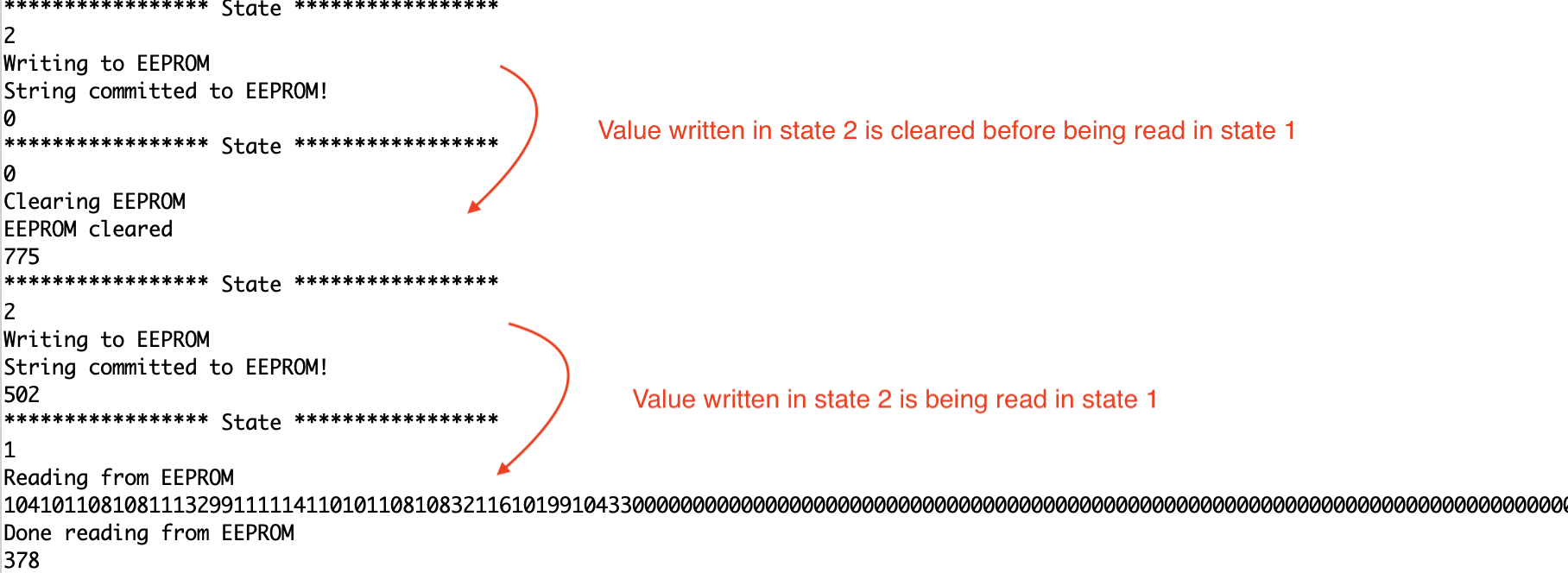
 A Read action should come right after the Write action to read values from the EEPROM.
b. Why is the code here all in the setup() functions and not in the loop() functions? To setup states everytime there is a switching of state. The setup is different for different states. We also want to take actions only when the state is changed and not on a loop constantly.
c. How many byte-sized data samples can you store on the Atmega328?
1024 byte-sized data samples
d. How would you get analog data from the Arduino analog pins to be byte-sized? How about analog data from the I2C devices? With int to byte char in Wire Library
byte loByte = lowByte(wordVal);
Serial.println(hiByte, HEX);
Serial.println(loByte,HEX);
e. Alternately, how would we store the data if it were bigger than a byte? (hint: take a look at the EEPROMPut example)
The method EEPROM.put() can write values larger than 255 (data types greater than 1 byte). We can use EEPROM.get() to read the data.
Upload your modified code that takes in analog values from your sensors and prints them back out to the Arduino Serial Monitor.
  basic state machine 2

  Modified to switch between states to write, read and clear EEPROM

 Demonstrates how to use a case statement to create a simple state machine.
 This code uses a potentiometer knob to select between 3 states.

 The circuit:
 * pot from analog in 0 to +5V
 * 10K resistor from analog in 0 to ground

 created 13 Apr 2010
 by Wendy Ju
 modified from switchCase by Tom Igoe

 12 Sep 2018
 Modified to switch between states to write, read and clear EEPROM
 */

#include <EEPROM.h>

const int numStates = 3;
const int sensorMin =0;
const int sensorMax = 1024;
const int EEPROMSIZE=1024;

int sensorPin = A2;    // select the input pin for the potentiometer
int ledPin = LED_BUILTIN;
int state,lastState = -1;

void setup() {
  // initialize serial communication:
  Serial.begin(9600);
  pinMode(ledPin, OUTPUT);
}

void loop() {

  // map the pot range to number of states :
  Serial.println(analogRead(sensorPin));
  delay(100);
  state = map(analogRead(sensorPin), sensorMin, sensorMax, 0, numStates);
  Serial.println("***************** State *****************");
  Serial.println(state);
  // do something different depending on the
  // range value:
  switch (state) {
  case 0:
    doState0();
    break;
  case 1:
    doState1();
    break;
  case 2:
    doState2();
    break;
  }
  lastState = state;
}
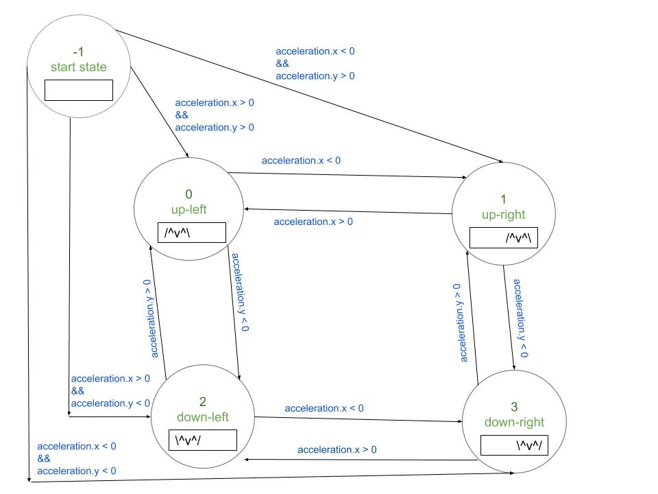
I built a toy to translate bird motion to the Serial Monitor.
When the bird flies up the feather opens. /^v^
When the bird flies down the feather closes. ^v^/
The bird moves left and right on the screen based on the movement of the accelerometer.
I am writing the state based on the movement of the accelerometer to the EEPROM. I am displaying the movement of the bird on the serial monitor based on the last state being read from the EEPROM.
a. Insert here a copy of your final state diagram.

a. Record and upload a short demo video of your logger in action. DEMO