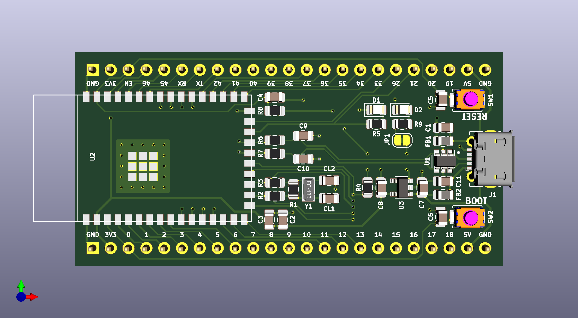
This board is a minimal breakout board for the new ESP32-S2-WROOM module from Espressif. It was designed with a few criteria in mind,
- Breakout as many pins as possible, if not all, from the module
- Be relatively easy for a hobbyist to order & assemble
- Use a minimal amount of components
To that end, a few choices were made,
- Designed in KiCad to be accessible to most people
- Use as little active components as possible
- Using 0805 (imperial) sized passives
- 0603 is on the edge of being easy to hand solder with an iron, so 0805 was used
- Ideally the board would be constructed using solder paste, a stencil and either some form of reflow oven or hot plate (even a skillet on a stove is fine)
- To have the boards cheaply manufactured by most turn-key pcb fab houses,
- Power traces should be at least 12 mil
- Signal traces should be at least 8 mil
- Vias should be 0.3mm drill size with a 0.6mm pad size
- No LGA parts, and ideally no QFN parts
The initial design was taken from the ESP32-S2-WROOM & ESP32-S2-WROOM-I Datasheet (v0.5) section 6. Peripheral Schematics Figure 5.
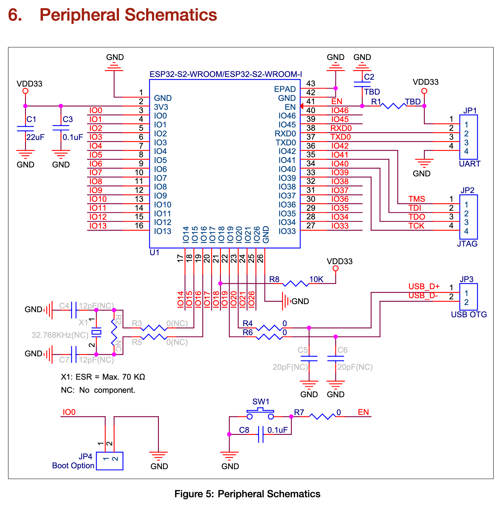
A few changes were made from this schematic.
- The USB data lines were directed to a USB Micro B connector
- No 0 resistor was used on the EN reset switch, just tied directly to the EN pin
- A switch was also used on IO0 for the boot mode, instead of a connector/header
- No separate connectors for UART/JTAG, all pins were broken out to 2.54mm/0.1" headers
A regulator which has high efficiencies (ie, low ground/quiescent current) is needed to get the best out of powering the device from higher voltages. The XC6220 has a hysterisis mode called "Green Operation" where the supply current current is much lower when the load current is below 2mA. The v1 of this board will also be a bit of a test for this regulator to see how it handles higher loads for wifi, and lower loads for sleep modes.
A few resources were useful when researching crystal and component choices.
- https://en.wikipedia.org/wiki/Pierce_oscillator
- http://ww1.microchip.com/downloads/en/AppNotes/00943A.pdf
- http://www.crystek.com/documents/appnotes/Pierce-GateIntroduction.pdf
- http://www.st.com/internet/com/TECHNICAL_RESOURCES/TECHNICAL_LITERATURE/APPLICATION_NOTE/CD00221665.pdf
A cheap crystal FC-135 with a max ESR of 70kOhms was used which fits on the KiCad 3215 pad. A few passive values will need to be tested for v1 to determine if they're even necessary.
The switches and connectors were chosen because they had footprints already in the KiCad library and are relatively accessible from most vendors.
A USBLC6-2SC6 was chosen for ESD protection of the USB power and data lines. This part was already available in KiCad and at a few distributors. An input capacitor was used fort this part, along with a ferrite bead before the 5v bus.
Another ferrite bead and capacitor was used between the shield and the ground. Probably not strictly necessary.