AVR Assembly: Project Intent
This project consists of notes and examples that I worked on while learning AVR assembly language programming for the first time.
Most or all of the examples assume use of the atmega168p. I
haven't used any headers for constants (which forces me to
really understand where these values come from) so these programs
will require adaptation to use with other AVR chips. The mods
required should be minor, though.
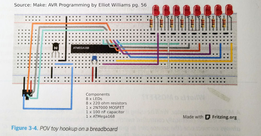
I've used a breadboard set up as per the example on page 56 of Make: AVR Programming by Elliot Williams.
Notes on AVR Assembly Setup
Setting Up Avra Assembler
Download the source code for avra from Github:
git@github.com:Ro5bert/avra.git
To build avra from scratch:
# cd into the root directory and run:
make
Check Programmer Connection
To check the device/programmer are working, run the command below (adjust for your programmer and chip):
avrdude -c usbasp -p m168

-c	programmer type
-p	AVR part/device
If you call avrdude -c without the part, it will give you
a list of available AVR device strings to choose from.
Note, my chips that look like m168p read as m168. Shrug?
Check Fuse Settings
You can check the fuse settings like:
avrdude -c usbasp -v -p m168
I noticed that it won't output information about the fuses if it thinks that the chip is wrong, however.
Building
To build using avra is trivial:
avra filename.asm
Flashing the Chip
avrdude -c usbasp -p m168 -U flash:w:hello.hex
You may also want to set the bitrate:
-b 57600
Obviously, change these settings however it makes sense for your particular setup.
A Note on Power
I noticed that the AVR chips can be a bit sensitive about VCC while being programmed, and that power via USB / programmer isn't always reliable. If something isn't working, try using a real power supply.
I/O Registers
AVR I/O registers are 64 bytes in data memory just after the 32
general working registers (0x20 - 0x5F). They include the PORT,
PIN, and DDR registers that control the m/c's pins.
Note that the Status Register (SREG) is one of the I/O registers.
AVR assembly language has instructions just for dealing with the I/O registers:
in In from I/O location
out Out from I/O location
cbi Clear a bit in an I/O register (first 32 registers)
sbi Set a bit in an I/O register (first 32 registers)
sbic Skip if bit in I/O register is 0
sbis Skip if bit in I/O register is 1
cbi and sbi only work with the first 32 I/O registers. All
PORT, PIN and DDR registers are in the first 32 memory locations.
c/sbi are useful for setting output to pins.
cbi and sbi use a pin number and not a mask, so you can only
set one pin at a time. in/out may be more efficient.
sbis/sbic can skip the next instruction based on a bit in an
I/O register, so you can use this to check the state of a pin.
Examples:
in	r15, DDRB	; load DDRB to r15
out	DDRB, r0	; load r0 to DDRB
I/O Addresses
There are Data Memory addresses, and there are I/O addresses. I/O addresses are mapped to data memory addresses, in order to be able to more efficiently access (some) I/O addresses.
Data memory address 0x20 maps to I/O 0x00.
You can see how this is useful: by renumbering the I/O addresses, it allows access to the first 32 in 5 bits.
Extended I/O Addresses
Extended I/O and SRAM allow for direct access using the lds and
sts instructions. Because these addresses are out of the range
of the first 32 I/O registers, we can't use in or out with
them. sts/lds work with the general purpose registers and up
to 64K of memory. Prefer to use these with r16-r31, it's more
efficient.
References
AVR Instruction Notes
(Random and incomplete)
ldi rd, imm
Loads an 8-bit number (0-255) into an upper half register (16-31)
out rd, r
Copies a number from a working register to an I/O register.
rjmp label
Jumps to the label. The label cannot be more than 204 instructions away. This is a "relative" jump.
