Disclaimer : This is not a Koolnova official integration and use at your own risk.
koolnova-BMS-Integration is an integration of koolnova system into Home Assistant using BMS (Building Management System) and Modbus RTU (RS485) protocol.
With BMS, owners can monitor and manage systems, such as air conditioning, heating, ventilation, lighting or energy supply systems. Some objectives of building automation are improved occupant comfort, efficient operation of building systems, reduction in energy consumption, reduced operating and maintaining costs and increased security.
Most building automation networks consist of a primary and secondary bus which connect high-level controllers with low-level controllers, input/output devices and a user interface. Physical connectivity between devices waq historically provided by dedicated optical fiber, ethernet, ARCNET, RS-232, RS-485 or a low-bandwidth special purpose wireless network.
Modbus is a client/server data communications protocol in the application layer of the OSI model. Modbus was developped for industrial applications, is relatively easy to deploy and maintain compared to other standards, and places few restrictions on the format of the data to be transmitted.
Communication standards or buses which is deployed for Modbus communication are:
- TCP/IP over Ethernet
- Asynchronous serial communication in a wide range of standards, technologies : EIA/TIA-232-E, EIA-422, EIA/TIA-485-A, fiber, radio frequency.
- Modbus PLUS, a high speed token passing network
Modbus standard defines MODBUS over Serial Line, a protocol over the Data link layer of the OSI model for the Modbus application layer protocol to be communicated over a serial bus. Modbus Serial Line protocol is a master/slave protocol which supports one master and multiple slaves in the serial bus. A serial bus for Modbus over Serial Line can maximum 247 slaves to communicate with 1 master, those slaves then must their unique address range from 1 to 247. Modbus over Serial Line has two transmission modes RTU and ASCII which are corresponded to two versions of the protocol, known as Modbus RTU and Modbus ASCII.
Modbus RTU (Remote Terminal Unit), makes use of a compact, binary representation of the data for protocol communication. The RTU format follows the commands/data with a cyclic redundancy check checksum as an error check mecahnism to ensure the reliability of data.
- An installation of Home Assistant with free USB port.
- A RS485 USB dongle (Example: DSD Tech SH-U11).
- A Koolnova air conditioning system (identifier: 100-CPNR00 or 100-CPND00) with areas defined.
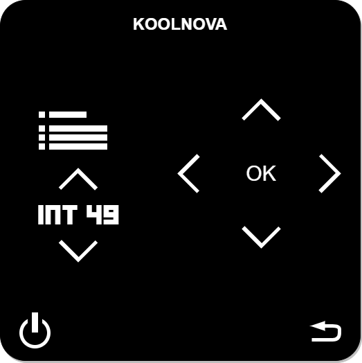
- Enabling Modbus communication on the master radio thermostat (INT 49).
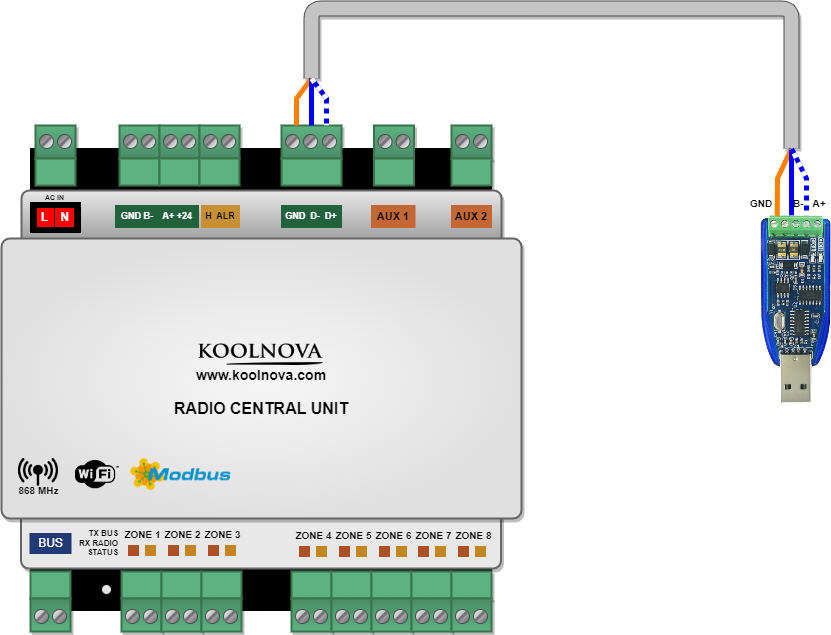
- Controller D+ to USB dongle A+
- Controller D- to USB dongle B-
- Controller GND to USB dongle GND
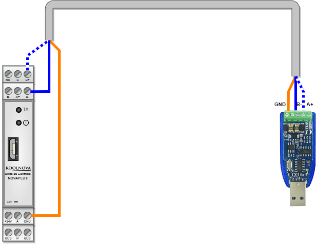
- Controller D+ to USB dongle A+
- Controller D- to USB dongle B-
- Controller GND to USB dongle GND
Install using HACS In HACS go to the three dots int the upper right corner choose add custom repository and add https://github.com/sinseman44/koolnova-BMS-Integration to the list.
Install manually Clone or copy this repository and copy the folder custom_components/koolnova_bms into /custom_components/koolnova_bms.
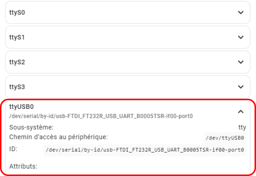
After plugging the USB dongle into the system, check that among the tty, it's recognized by Home Assistant.
Example : ttyUSB0 is the node added for the device. The absolute path of this node (eg: /dev/ttyUSB0) will be used in the component configuration.
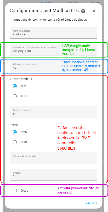
The first page after installing the component is the Modbus BMS configuration. All serial fields are filled with default values defined by Koolnova.
Adapt the fields according to your own configuration.
Note
Each control unit has a specific address (default 49). Possible addresses are 1 to 247.
After validation of the serial configuation, the component will test if it can communicate with the koolnova system. If not, an error occur.
Warning
some users encountered a problem with the slave Modbus address. Enter address “1” instead of the default (49) and check if this validate this step.
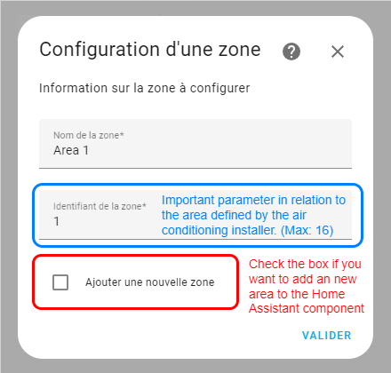
The next installation page is the area configuration.
This page appears for each area that must be configured.
The checkbox must be filled before validation if you want to configure a new area.
The area configuration ends with no new area.
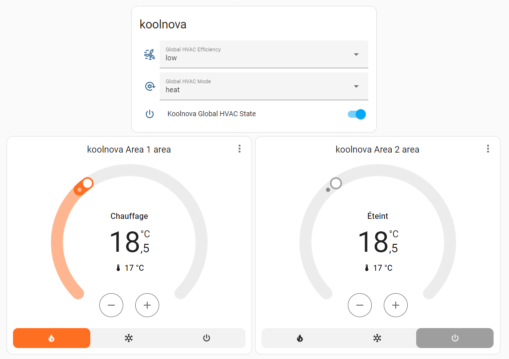
- Integrates local API to read/write Modbus koolnova registers
- Provides
climatefor each area,sensor,selectandswitch
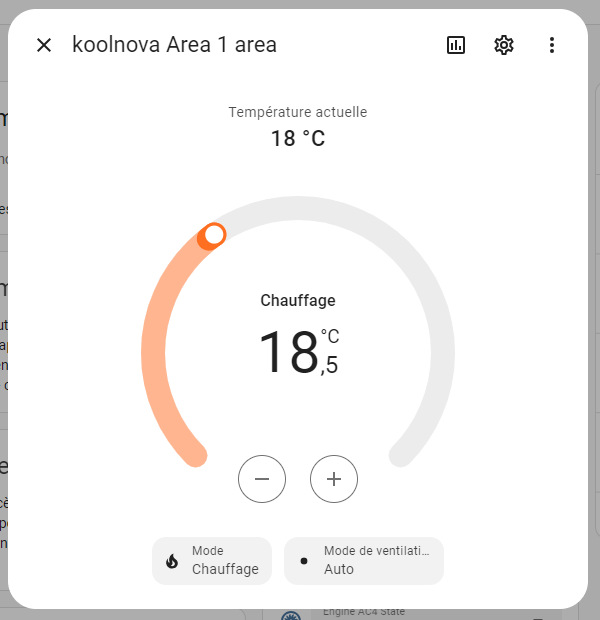
The following parameters can be controlled for the climate platform entities:
- Power
- Target temperature (celcius, Min: 15°C -> Max: 35°C)
- Operation mode (HVAC mode: Heating/Refeshing)
- Fan mode (HVAC mode)
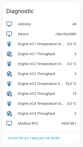
The following attributes are available for diagnostic sensor platform entities:
-
Modbus serial (Device, Address, port, ...)
-
Target temperature (celcius) and throughput for each engine (maximum 4):
- Target temperature: Min: 15°C -> Max: 35°C
- Troughput: int value between 0 (engine stopped) to 15 (maximum troughput)
-
Target temperature (celcius) for each area:
- 0°C to 50°C
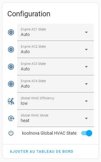
The following parameters can be controlled for the select platform entities:
-
Global operation mode (HVAC mode)
- cold
- heat
- heating floor (need a specific hardware module, identifier: 100-MSR002)
- refreshing floor and refreshing air (need a specific hardware module, identifier: 100-MSR002)
- heating floor and heating air (need a specific hardware module, identifier: 100-MSR002)
-
Global efficiency defined the balance point between efficiency and speed of the area system.
- Lower: the set temperature is reached sooner
- Higher: better efficiency
-
Engine state: int value which represents the flow programming of the system engines
- 1: Manual minimum
- 2: Manual medium
- 3: Manual high
- 4: Automatic
The following parameter can be controlled for the switch platform entitie:
- Global HVAC State (stopped or running)
Whenever you write a bug report, it helps tremendously if you indicate sufficient debug logs directly (otherwise we will just ask for them and it will take longer). So please enable debug logs like this and include them in your issue:
logger:
  default: warning
  logs:
    custom_components.koolnova_bms: debug


