Udacity self-driving car nanodegree Project 3 solution: neural network that drives a simulated car around a track autonomously. The network is implemented in Keras, and trained on recorded behavior of a human driver.
video.mp4 shows the network in action.
The goals / steps of this project are the following:
- Use the simulator to collect data of good driving behavior
- Build a convolution neural network in Keras that predicts steering angles from images
- Train and validate the model with a training and validation set
- Test that the model successfully drives around track one without leaving the road
- Summarize the results with a written report
The Keras implementation of my model can be found in model.py.
model.h5 is a saved Keras model containing a version of my trained network that reliably steers the car all the way around the track in my tests.
Rubric points are addressed individually below.
Files Submitted & Code Quality
1. Submission includes all required files and can be used to run the simulator in autonomous mode
My project includes the following files:
- model.py: Keras implementation of model, as well as code to load data and train the model
- drive.py: Connects to Udacity simulator (not provided) to feed image data from the simulator to my model, and angle data from my model back to the simulator
- model.h5: A saved Keras model, trained using model.py, capable of reliably steering the car all the way around Track 1
- video.mp4: Video of the car driving around the track, with steering data supplied by model.h5
- writeup_report.md
2. Submission includes functional code
If you clone this repository, start the Udacity simulator (not provided), and run
python drive.py model.h5you should see the car drive around the track autonomously without leaving the road.
3. Submission code is usable and readable
Please refer to model.py.
Model Architecture and Training Strategy
1. An appropriate model architecture has been employed
My final model is a Keras implementation of the Nvidia convolutional neural network designed specifically to generate steering data for self-driving cars based on camera inputs. See "Final model architecture" below for a description of the layers.
2. Attempts to reduce overfitting in the model
I split the data into training and validation sets to diagnose overfitting, but when I used the fully augmented data set (described in "Creation of the Training Set" below), overfitting did not appear to be a significant problem. Loss on the validation set was comparable to loss on the test set at the end of training. Apparently, the (shuffled and augmented) training set was large enough to allow the model to generalize to the validation data as well, even without dropout layers.
I also made sure to monitor loss while the network was training to make sure validation loss was not increasing for later epochs.
3. Model parameter tuning
I used an Adams optimizer, so tuning learning rate was not necessary. The one parameter I did tune was the correction angle added to (subtracted from) the driving angle to pair with an image from the left (right) camera.
After trying several outlier values, I found a range of correction angles that resulted in good driving performance. I trained the network for correction angles of 0.6, 0.65, 0.7, 0.75 and 0.8. Training with larger correction angles resulted in snappier response to tight turns, but also a tendency to overcorrect on shallower turns, which makes sense. The model.h5 file accompanying this submission was trained with a correction angle of 0.65. Sometimes it approaches the side of the road, or sways side to side, but corrects itself robustly. I actually like the mild swaying, because it shows the car knows how to recover.
4. Appropriate training data
See "Creation of the Training Set" below.
Model Architecture and Training Strategy
1. Solution Design Approach
All training was conducted on my laptop. I've set up TensorFlow to use my installed GPU (an Nvidia Geforce GTX 960M GPU, Maxwell architecture).
I began by training a 1-layer fully connected network, using only data from the center camera, just to get the data pipeline working.
Next I implemented LeNet in Keras, to see how it would perform.
I trained LeNet using only data from the center camera.
It sometimes got the car around the first corner and onto the bridge.
Next I implemented a cropping layer as the first layer in my network. This removed the top 50 and bottom 20 pixels from each input image before passing the image on to the convolution layers. The top 50 pixels tended to contain sky/trees/horizon, and the bottom 20 pixels contained the car's hood, all of which are irrelevant to steering and might confuse the model.
I then decided to augment the training dataset by additionally using images from the left and right cameras, as well as a left-right flipped version of the center camera's image. This entire training+validation dataset was too large to store in my computer's RAM: 8036 samples x 160x320x3 x 4 bytes per float x 4 images per sample (center,left,right,flipped) = about 20 GB. model.py began swapping RAM to the hard drive while running, which made the code infeasibly slow. I implemented Python generators to serve training and validation data to model.fit_generator(). This made model.py run much faster and more smoothly. However, the car still failed at the first of the two sharp curves after the bridge.
I then implemented the Nvidia neural network architecture found here: https://devblogs.nvidia.com/parallelforall/deep-learning-self-driving-cars/. This network is purpose-built for end-to-end training of self-driving car steering based on input from cameras, so it is ideal for the simulator.
The only remaining step was to tune the correction applied to the angle associated with the right and left camera images, as described in "Model parameter tuning" above. I found that the trained network reliably steered the car all the way around the track for several different choices of correction angle. It was really cool to see how the choice of correction angle influenced the car's handling. As I noted earlier, training the network with high correction angles resulted in quick, sharp response to turns, but also a tendency to overcorrect. Training with smaller correction angles resulted in less swaying back and forth across the road, but also a gentler (sometimes too gentle) response to sharp turns.
Actually, it was incredibly cool to see the whole thing work. It was frustrating at times too...but we won't go into that.
2. Final Model Architecture
For informational purposes, output dimensions of convolution layers are shown, with output heights computed according to out_height = ceil( ( in_height - kernel_height + 1 )/stride_height. Output widths are computed similarly.
When adding a layer, Keras automatically computes the output shape of the previous layer, so it is not necessary to compute output dimensions manually in the code.
| Layer | Description |
|---|---|
| Input | 160x320x3 RGB image A |
| Cropping | Crop top 50 pixels and bottom 20 pixels; output shape = 90x320x3 |
| Normalization | Each new pixel value = old pixel value/255 - 0.5 |
| Convolution 5x5 | 5x5 kernel, 2x2 stride, 24 output channels, output shape = 43x158x24 |
| RELU | |
| Convolution 5x5 | 5x5 kernel, 2x2 stride, 36 output channels, output shape = 20x77x36 |
| RELU | |
| Convolution 5x5 | 5x5 kernel, 2x2 stride, 48 output channels, output shape = 8x37x48 |
| RELU | |
| Convolution 5x5 | 3x3 kernel, 1x1 stride, 64 output channels, output shape = 6x35x64 |
| RELU | |
| Convolution 5x5 | 3x3 kernel, 1x1 stride, 64 output channels, output shape = 4x33x64 |
| RELU | |
| Flatten | Input 4x33x64, output 8448 |
| Fully connected | Input 8448, output 100 |
| Dropout | Set units to zero with probability 0.5 |
| Fully connected | Input 100, output 50 |
| Fully connected | Input 50, output 10 |
| Fully connected | Input 10, output 1 (labels) |
If my layer size math is correct, it does seem like the first fully connected layer has a very large number of parameters (8448x100) and therefore might overfit. I added a dropout layer after the first fully connected layer to guard against this possibility. For the record, the network also performs just fine without the dropout layer.
3. Creation of the Training Set & Training Process
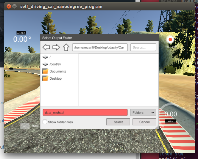
Unfortunately, I had trouble recording my own training data on my system (Ubuntu 16.04). When I tried to select an output directory from within linux_sim.x86_64, the directory appeared red, and the executable did nothing:
Choice of directory did not appear to matter.
The only thing I could think of was that it was a permissions issue. I chmod 777ed my output
directory, and even ran the simulator as root, but the problem persisted.
I therefore decided to use the provided training data, which was read in from driving_log.csv. Each line of driving_log.csv corresponded to one sample. Each sample contained a relative path to center, left, and right camera images, as well as the current driving angle, throttle, brake, and speed data.
For each data sample, I used all three provided images (from the center, left, and right cameras) and also augmented the data with a flipped version of the center camera's image.
Here's an example image from the center camera.
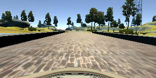
Here's an image at the same time sample from the left camera.
This image also approximates what the center camera would see if the car were too far to the left.
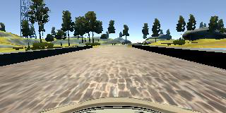
Here's an image at the same time sample from the the right camera.
This image also approximates what the center camera would see if the car were too far to the right.
Here's the image from the center camera, flipped left<->right.
When the car is driving in the simulator, it will be fed data from the center camera only. The left (right) camera gives an effective view of what the center camera would see if the car is too far to the left (right); in such cases the car should correct by veering to the right (left). Therefore, when we add the left and right camera images to the training and validation sets, we should associate angles with them that represent what the steering angle should be if the center camera were seeing the image recorded by the left or right camera, in other words, what the car should do if the center camera were at the point on the road occupied by the left or right camera.
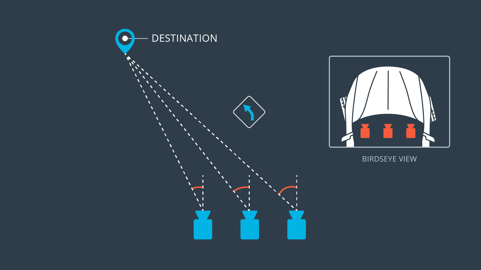
Say at a given point in time the car is driving with a certain steering angle to stay on the road. If the car suddenly shifted so that the center camera was in the spot formerly occupied by the left camera, the driving angle would have to be adjusted clockwise (a correction added) to stay on the road. If the car shifted so that the center camera was in the spot formerly occupied by the right camera, the driving angle would have to be adjusted counterclockwise (a correction subtracted) to stay on the road. Here's a diagram from the Udacity lesson. You can see that a line from the left camera's position to the same destination is further clockwise, while a line from the right camera's position to the same destination is further counterclockwise.
Adding the left and right images to the training set paired with corrected angles should help the car recover when the center-camera's image veers too far to the left or right.
The angle associated with each flipped image is the negative of the current driving angle, because it is the angle the car should steer if the road were flipped left<->right. The track is counterclockwise, so unaugmented training data contains more left turns than right turns. Flipping the center-camera image and pairing it with a corresponding flipped angle adds more right-turn data, which should help the model generalize.
Images were read in from files, and the flipped image added, using a Python generator. The generator processed lines of the file that stored image locations along with angle data (driving_log.csv) in batches of 32, and supplied data to model.fit_generator() in batches of 128 (each line of driving_log.csv was used to provide a center-camera, left-camera, right-camera, and center-camera-flipped image).
The generator also shuffled the array containing the training samples prior to each epoch, so that training data would not be fed to the network in the same order.
The data set provided 8036 samples, each of which had a path to a center, left, and right image. sklearn.model_selection.train_test_split() was used to split off 20% of the samples to use for validation. For each sample, the center-flipped image was created on the fly within the generator. Therefore, my network was trained on a total of floor(8036x0.8) x 4 = 25,712 image+angle pairs, and validated on a total of ceil(8036x0.2) x 4 = 6432 image+angle pairs.
A separate generator was created for training data and validation data. The training generator provided images and angles derived from samples in the training set, while the validation generator provided images and data derived from samples in the validation set.
I trained the model for 5 epochs using an Adams optimizer, which was probably more epochs than necessary, but I wanted to be sure the validation error was plateauing. As noted previously, I did make sure the validation error was not increasing for later epochs.


