This is an Akka Cluster project that includes an example use of Cluster Sharding, Cluster Singleton, the Receptionist, Cluster Subscriptions, cluster dashboard, and cluster sharding viewer.
This project is one in a series of projects that starts with a simple Akka Cluster project and progressively builds up to examples of event sourcing and command query responsibility segregation - CQRS.
The project series is composed of the following GitHub repos:
- akka-typed-java-cluster
- akka-typed-java-cluster-aware
- akka-typed-java-cluster-singleton
- akka-typed-java-cluster-sharding (this project)
- simulator and visualizer Akka Cluster Sharding demo
- woe-sim an example o Akka Persistence
- woe-twin an example of Akka Persistence and Akka Projections
Each project can be cloned, built, and runs independently of the other projects.
According to the Akka documentation, "Cluster sharding is useful when you need to distribute actors across several nodes in the cluster and want to be able to interact with them using their logical identifier, but without having to care about their physical location in the cluster, which might also change over time."
The common usage for cluster sharding is to distribute and engage with individual actors across the cluster. Each of these distributed actors is used to handle messages that are intended for a specific entity. Each entity represents a thing, such as a bank account or a shopping cart. Entities each have a unique identifier, such as an account or shopping cart identifier.
In this example project, the entities represent simple identifier and value. In a real application, entities represent real things, such as bank accounts. Each entity handles incoming messages. These messages are either commands, which are requests to chage the state of the entity. Other messages are query requests that are used to retrieve entity information.
Two actors are used to simulate clients that are sending messages to entities. The EntityCommandActor and the EntityQueryActor randomly generate messages to specific entities. These two actors are used to simulate incoming service requests. In a real implementation, the service would receive incoming messages, for example from an HTTP request, and forward those messages to specific entities to handle the request messages.
The process of forwarding these messages to the right entities, which could be distributed across multiple JVMs running in a cluster, is handled by cluster sharding. To send a message to an entity the sender simply sends the message to a shard region actor. The shard region actor is responsible for forwarding the message to the correct entity actor. The actual mechanics of this process is described in the Cluster Sharding concepts section of the cluster sharding documentation.
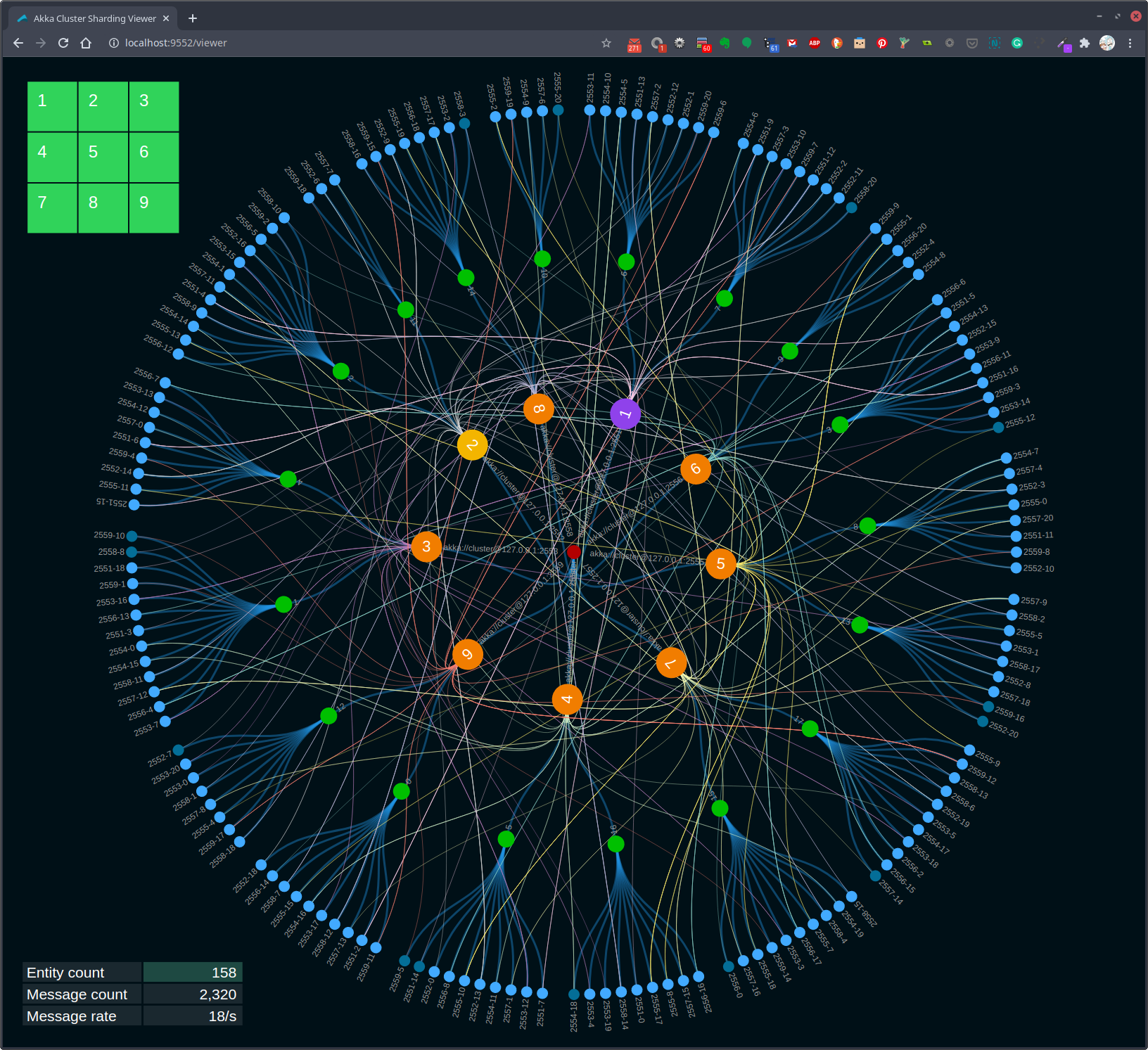
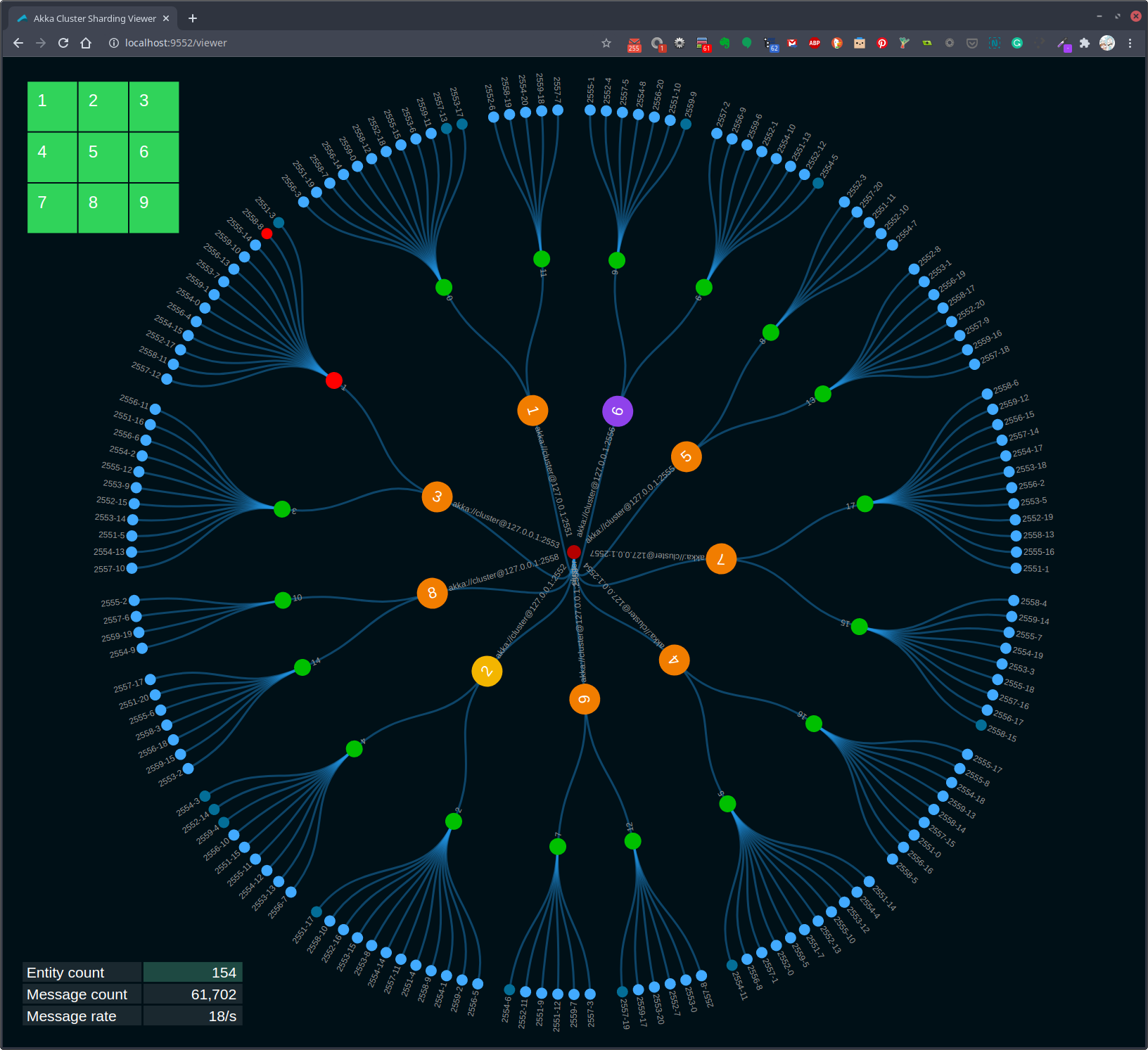
Figure 1, Visualization of cluster sharding
The visualization in Figure 1 shows an example of cluster sharding. The blue leaf circles represent the entity actors. Each entity actor represents the state of an entity. The green circles that connect to the entity circles represent the running shard actors. In the example system there 18 shards configured. The shards connect to the orange shard region actors. These orange circles also represent other actors, such as the entity command and query actors. Also, the orange circles represent the root of the actor system on each cluster node. The grid on the top left represents the state of each of the nine nodes in the cluster. Green tiles in the grid indicate running cluster nodes. Nodes that are down or have no running entity actors are gray.
Cluster sharding is started in the Main class. The startClusterSharding method contains the code for initializing cluster sharding for the demo entity actor. See the
Cluster Sharding documentation for a description of how this works.
  private static void startClusterSharding(final ActorSystem<?> actorSystem, ActorRef<HttpServer.Statistics> httpServerActorRef) {
    ClusterSharding clusterSharding = ClusterSharding.get(actorSystem);
    clusterSharding.init(
      Entity.of(
        EntityActor.entityTypeKey,
        entityContext ->
          EntityActor.create(entityContext.getEntityId(), httpServerActorRef)
      )
      .withStopMessage(EntityActor.Passivate.INSTANCE)
    );
  }
The EntityActor is much like any other actor, it receives and processes incoming messages. The following createReceive method implementation defines the three messages that this actor handles.
  @Override
  public Receive<Command> createReceive() {
    return newReceiveBuilder()
    .onMessage(ChangeValue.class, this::onChangeValue)
    .onMessage(GetValue.class, this::onGetValue)
    .onMessage(Passivate.class, msg -> onPassivate())
    .build();
  }
When a ChangeValue messages is received the onChangeValue method, shown below, is invoked.
  private Behavior<Command> onChangeValue(ChangeValue changeValue) {
    if (state == null) {
      state = new State(changeValue.id, changeValue.value);
      log().info("initialize {}", state);

      changeValue.replyTo.tell(new ChangeValueAck("initialize", changeValue.id, changeValue.value));
      notifyHttpServer("start");
    } else {
      log().info("update {} {} -> {}", state.id, state.value, changeValue.value);
      state.value = changeValue.value;
      changeValue.replyTo.tell(new ChangeValueAck("update", changeValue.id, changeValue.value));
    }
    return this;
  }
The onChangeValue method's logic is relatively simple in this example. In a real entity actor implementation, the message handler messages typically involve some form of command/request validation followed by persisting zero, one or more events, followed by a state change after completing a persist operation.
One thing to take note of is how this actor replies to the command message sender. When a reply is sent after the entity actor is first started is slightly different than when replying after the first command.
      changeValue.replyTo.tell(new ChangeValueAck("initialize", changeValue.id, changeValue.value));

      changeValue.replyTo.tell(new ChangeValueAck("update", changeValue.id, changeValue.value));
As each incoming command is processed, the notifyHttpServer method is also invoked. This method is used to send a message to the HttpServerActor. Each entity actor notifies the HTTP server actor when each message is received. These notifications are used to modify the cluster sharding state data rendered in the Cluster Sharding web viewer.
  private void notifyHttpServer(String action) {
    final EntityAction entityAction = new EntityAction(memberId, shardId, entityId, action);
    final BroadcastEntityAction broadcastEntityAction = new BroadcastEntityAction(entityAction);
    httpServerActorRef.tell(broadcastEntityAction);
  }
The notifyHttpServer method sends a BroadcastEntityAction message. When a broadcastEntityAction message is received by an HttpServerActor it is handled in the onBroadcastEntityAction method shown below.
  private Behavior<HttpServer.Statistics> onBroadcastEntityAction(BroadcastEntityAction broadcastEntityAction) {
    serviceInstances.stream()
        .forEach(httpServeractorRef -> httpServeractorRef.tell(broadcastEntityAction.entityAction));
    return Behaviors.same();
  }
There is one instance of an HttpServerActor running on each node in the cluster. When these actors start up they register and subscribe with the Akka Cluster Receptionsit. The receptionist is used by each of the HttpServerActor instance to communicate with each other. In this case, when notified that a given entity actor has started or stopped, this information is broadcast from the receiving actor to all of the other `HttpServerActor' instance running in the cluster.
When actors register with the receptionist, they are sharing their actor reference with the receptionist. The receptionist adds the registrant's actor ref to a list and then sends the updated list to all subscribers. In this case, each HttpServerActors both register and subscribe with the receptionist.
The code in the onBroadcastEntityAction method sends an EntityAction message to each receptionist subscriber, all of the currently running HttpServerActors. When an HttpServerActor receives a EntityAction message the onNotifyEntityAction method is invoked.
  private Behavior<HttpServer.Statistics> onNotifyEntityAction(HttpServer.EntityAction entityAction) {
    log().info("{}", entityAction);
    httpServer.load(entityAction);
    return Behaviors.same();
  }
The onNotifyEntityAction method updates the information used in the web cluster sharding viewer.
Messages are sent to entity actors from two other actors, EntityCommandActor and EntityQueryActor. These two actors use a timer to send command and query messages to random entity actors periodically.
  private Behavior<EntityActor.Command> onTick() {
    final String entityId = EntityActor.entityId(nodePort, (int) Math.round(Math.random() * entitiesPerNode));
    final EntityActor.Id id = new EntityActor.Id(entityId);
    final EntityActor.Value value = new EntityActor.Value(new Date());
    final EntityRef<Command> entityRef = clusterSharding.entityRefFor(EntityActor.entityTypeKey, entityId);
    entityRef.tell(new EntityActor.ChangeValue(id, value, actorContext.getSelf()));
    return this;
  }
These messages are sent via the onTick method. Note the process used to send these messages to the entity actors. The actual location of the entity actors is handled by cluster sharding. The sending actors send messages to cluster sharding, and it routes the messages to the targeted entity actor.
git clone https://github.com/mckeeh3/akka-typed-java-cluster-sharding.git
cd akka-typed-java-cluster-sharding
mvn clean package
The Maven command builds the project and creates a self contained runnable JAR.
The project contains a set of scripts that can be used to start and stop individual cluster nodes or start and stop a cluster of nodes.
The main script ./akka is provided to run a cluster of nodes or start and stop individual nodes.
Run the akka script with no parameters to see the available options.
./akkaThis CLI is used to start, stop and view the dashboard nodes in an Akka cluster.
These commands manage the Akka cluster as defined in this project. A cluster
of nodes is started using the JAR file built by this project's Maven POM file.
Cluster commands are used to start, stop, view status, and open the Akka cluster dashboard.
./akka cluster start N | stop | status | dashboard [N]
./akka cluster start [N] # Starts one or more cluster nodes as specified by [N] or default 9, which must be 1-9.
./akka cluster stop # Stops all currently cluster nodes.
./akka cluster status # Shows an Akka Management view of the cluster status/state.
./akka cluster dashboard [N] # Opens an Akka cluster dashboard web page hosted on the specified [N] or default 1, which must be 1-9.
./akka cluster viewer [N] # Opens an Akka cluster sharding viewer web page hosted on the specified [N] or default 1, which must be 1-9.
Node commands are used to start, stop, kill, down, or tail the log of cluster nodes.
Nodes are started on port 255N and management port 855N, N is the node number 1-9.
./akka node start N | stop N | kill N | down N | tail N
./akka node start N... # Start one or more cluster nodes for nodes 1-9.
./akka node stop N... # Stop one or more cluster nodes for nodes 1-9.
./akka node kill N... # Kill (kill -9) one or more cluster nodes for nodes 1-9.
./akka node down N... # Down one or more cluster nodes for nodes 1-9.
./akka node tail N # Tail the log file of the specified cluster node for nodes 1-9.
Net commands are used to block and unblock network access to cluster nodes.
./akka net block N | unblock | view | enable | disable | partition
./akka net block N... # Block network access to node ports, ports 255N, nodes N 1-9.
./akka net unblock # Reset the network blocking rules.
./akka net view # View the current network blocking rules.
./akka net enable # Enable packet filtering, which enables blocking network access to cluster nodes. (OSX only)
./akka net disable # Disable packet filtering, which disables blocking network access to cluster nodes. (OSX only)
./akka net localhost2 # Create or remove IP alias 127.0.0.2
./akka net partition # Partition 127.0.0.2 on or off
The cluster and node start options will start Akka nodes on ports 2551 through 2559.
Both stdin and stderr output is sent to a log files in the /tmp directory using the file naming convention /tmp/<project-dir-name>-N.log.
Start a cluster of nine nodes running on ports 2551 to 2559.
./akka cluster startStarting 9 cluster nodes
Start node 1 on port 2551, management port 8551, HTTP port 9551
Start node 2 on port 2552, management port 8552, HTTP port 9552
Start node 3 on port 2553, management port 8553, HTTP port 9553
Start node 4 on port 2554, management port 8554, HTTP port 9554
Start node 5 on port 2555, management port 8555, HTTP port 9555
Start node 6 on port 2556, management port 8556, HTTP port 9556
Start node 7 on port 2557, management port 8557, HTTP port 9557
Start node 8 on port 2558, management port 8558, HTTP port 9558
Start node 9 on port 2559, management port 8559, HTTP port 9559
Stop all currently running cluster nodes.
./akka cluster stopStop node 1 on port 2551
Stop node 2 on port 2552
Stop node 3 on port 2553
Stop node 4 on port 2554
Stop node 5 on port 2555
Stop node 6 on port 2556
Stop node 7 on port 2557
Stop node 8 on port 2558
Stop node 9 on port 2559
Stop node 3 on port 2553.
./akka node stop 3Stop node 3 on port 2553
Stop nodes 5 and 7 on ports 2555 and 2557.
./akka node stop 5 7Stop node 5 on port 2555
Stop node 7 on port 2557
Start node 3, 5, and 7 on ports 2553, 2555 and 2557.
./akka node start 3 5 7Start node 3 on port 2553, management port 8553, HTTP port 9553
Start node 5 on port 2555, management port 8555, HTTP port 9555
Start node 7 on port 2557, management port 8557, HTTP port 9557
Start a cluster of four nodes on ports 2551, 2552, 2553, and 2554.
./akka cluster start 4Starting 4 cluster nodes
Start node 1 on port 2551, management port 8551, HTTP port 9551
Start node 2 on port 2552, management port 8552, HTTP port 9552
Start node 3 on port 2553, management port 8553, HTTP port 9553
Start node 4 on port 2554, management port 8554, HTTP port 9554
Again, stop all currently running cluster nodes.
./akka cluster stopThe ./akka cluster status command displays the status of a currently running cluster in JSON format using the
Akka Management
extension
Cluster Http Management.
Please see The Cluster Dashboard in the Cluster Singleton project. This project starts with the previous Akka Cluster Singleton project than adding an Akka Cluster Sharding example. Therefore all of the documentation of the last project also applies to this project.
The viewer can be opened on any currently running cluster node. First, start a cluster.
./akka cluster startStarting 9 cluster nodes
Start node 1 on port 2551, management port 8551, HTTP port 9551
Start node 2 on port 2552, management port 8552, HTTP port 9552
Start node 3 on port 2553, management port 8553, HTTP port 9553
Start node 4 on port 2554, management port 8554, HTTP port 9554
Start node 5 on port 2555, management port 8555, HTTP port 9555
Start node 6 on port 2556, management port 8556, HTTP port 9556
Start node 7 on port 2557, management port 8557, HTTP port 9557
Start node 8 on port 2558, management port 8558, HTTP port 9558
Start node 9 on port 2559, management port 8559, HTTP port 9559
Wait for a few moments for the cluster nodes to start, then use the following command to open the cluster sharding viewer.
./akka cluster viewer 2Note that the above command opened the viewer using the HTTP server running on node 2.
Figure 2, Visualization of cluster sharding
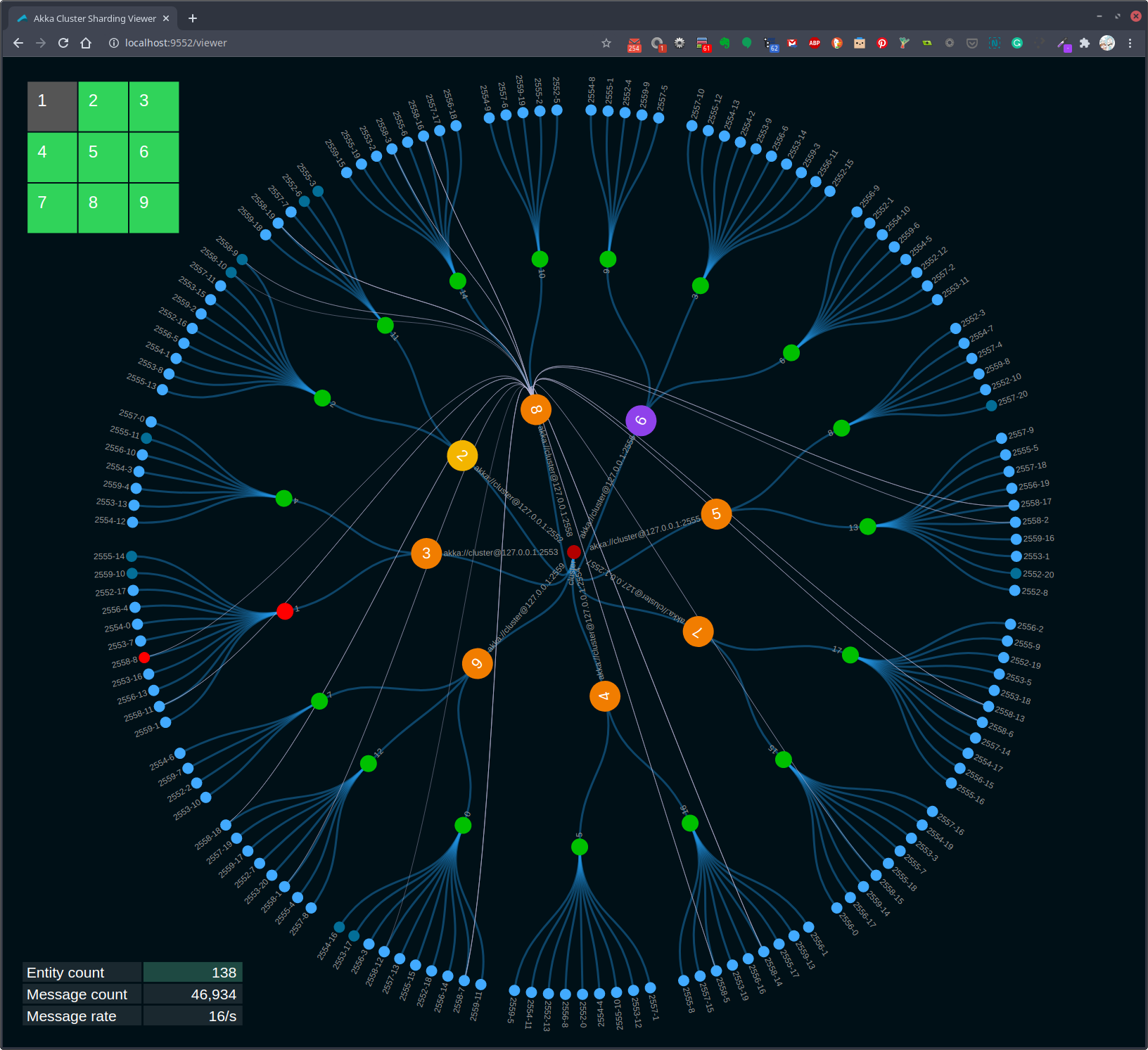
The above image shows the viewer of an Akka Cluster running nine nodes. Note the colors of nodes 1 and 2. The purple color of node 1 indicates this is the oldest running node and the node where cluster singleton actors are currently running. The yellow color of node 2 shows that this is the node that the viewer web page is connected to from the browser.
The reason for highlighting the oldest node is to show how cluster singleton actors move when the oldest node changes. The image below shows what happened when node 1 is stopped. In this case, when node 1 is stopped, node 6 becomes the oldest node. Note that the color of node 3 has changed.
You can stop selected cluster nodes from the viewer's web page by clicking one of the nodes in the top left grid. In this example, node 1 was stopped by clicking node 1 in the grid.
Figure 3, Cluster singleton moves to new oldest node
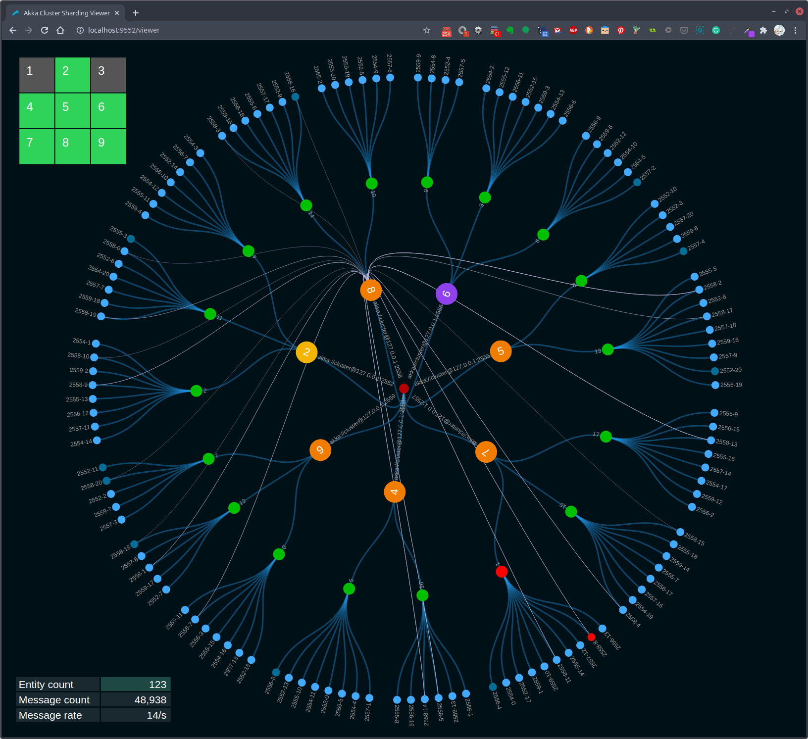
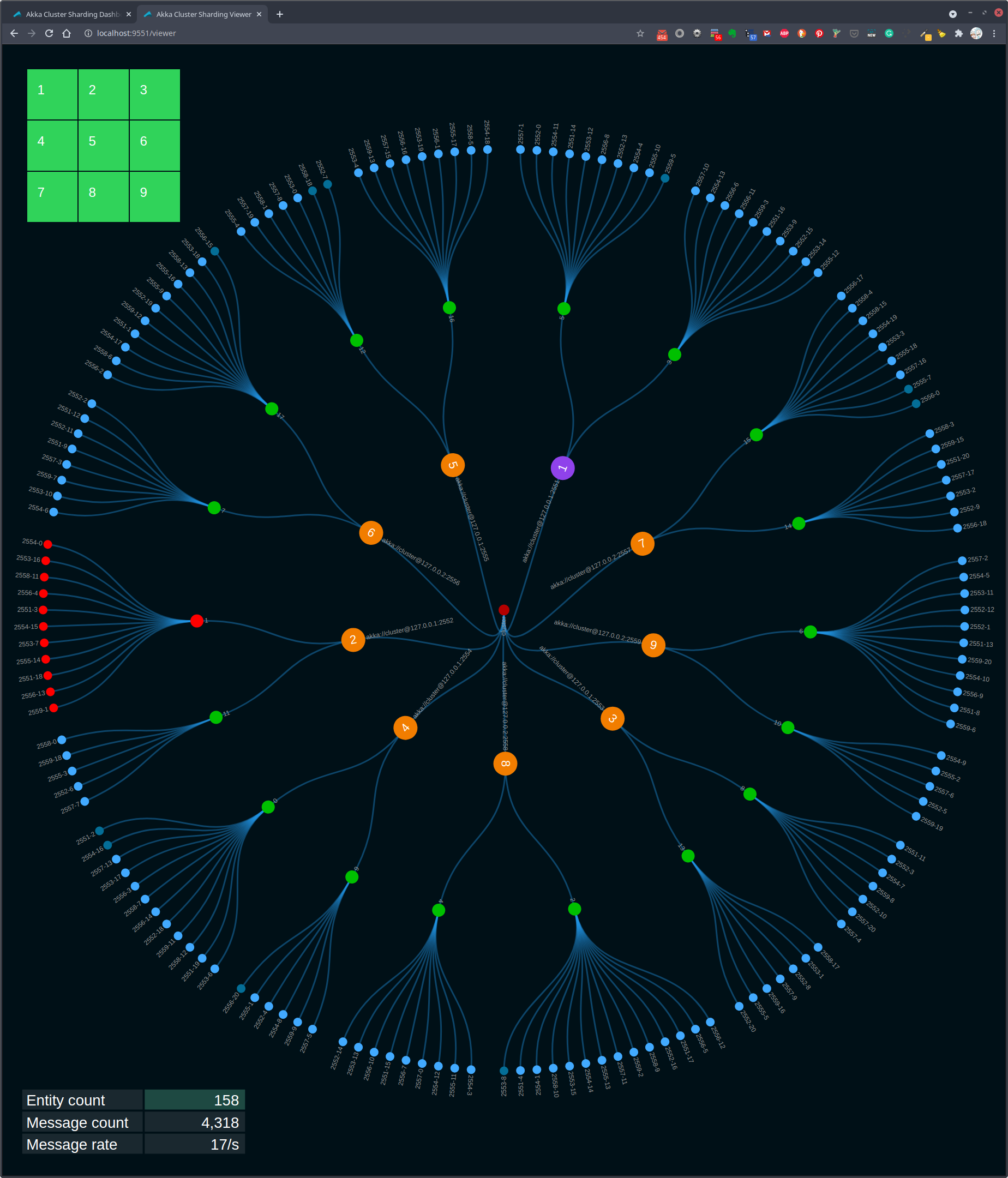
It is also possible to highlight and track the selected entity actors. When you click one of the entity actor circles, its color changes to red. Note that entity actor 2558-8 in the above image is red. Also, note that the parent shard actor's color is red.
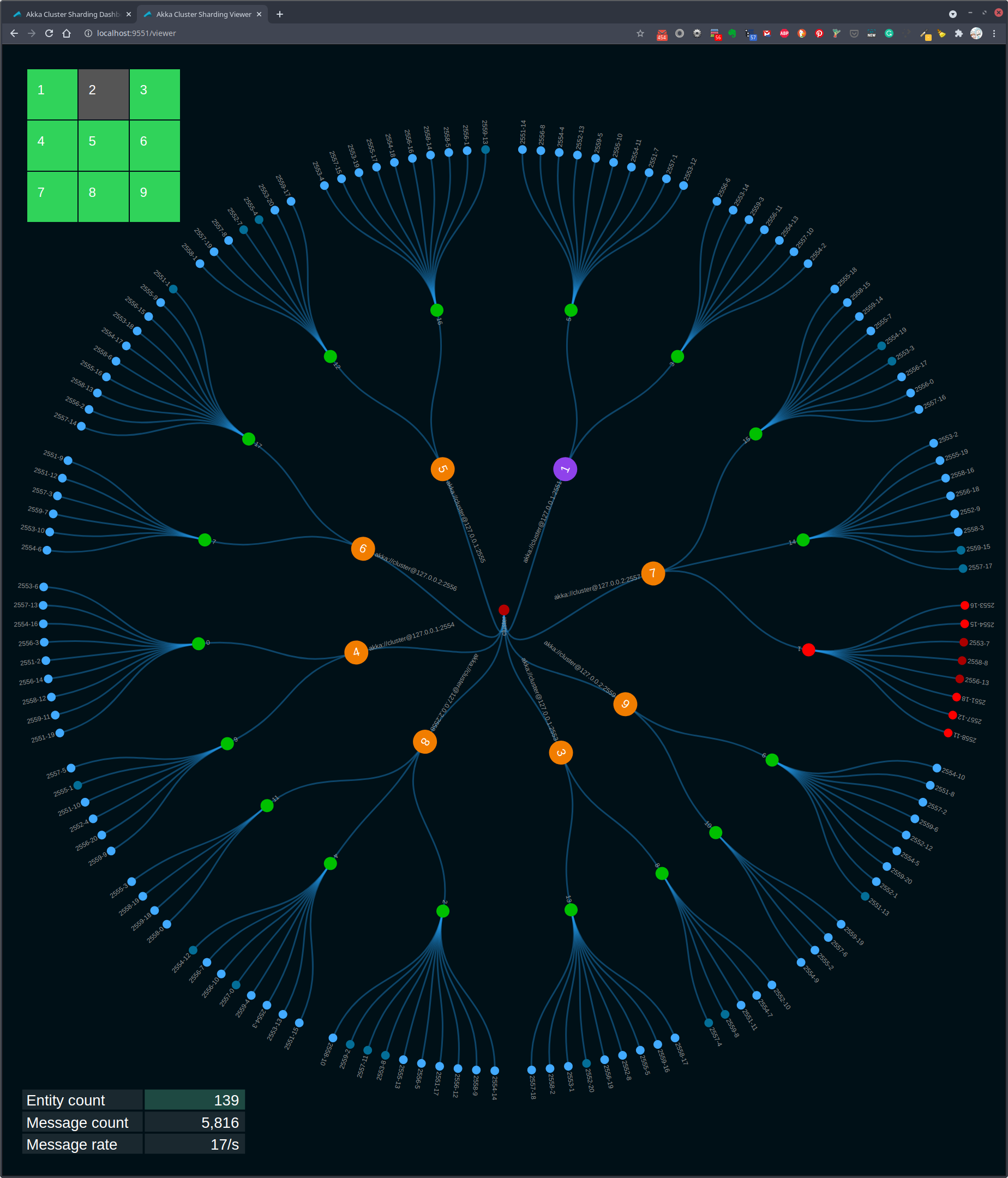
Highlighting entity and shard actors allows you to watch how entity and shard actors move between nodes as the cluster expands and contracts. Here, node 3 is stopped by clicking node 3 in the top-left grid.
Figure 4, Shard and entity actors restarted on new node
In the above image, you can see that entity actor 2558-8 of shard 1 has "moved" to node 7. The actors are not actually moved. A new instance of each actor is started on the new nodes. Also, note that nodes 1 and 3 in the top-left grid are dark to indicate that they are no longer running.
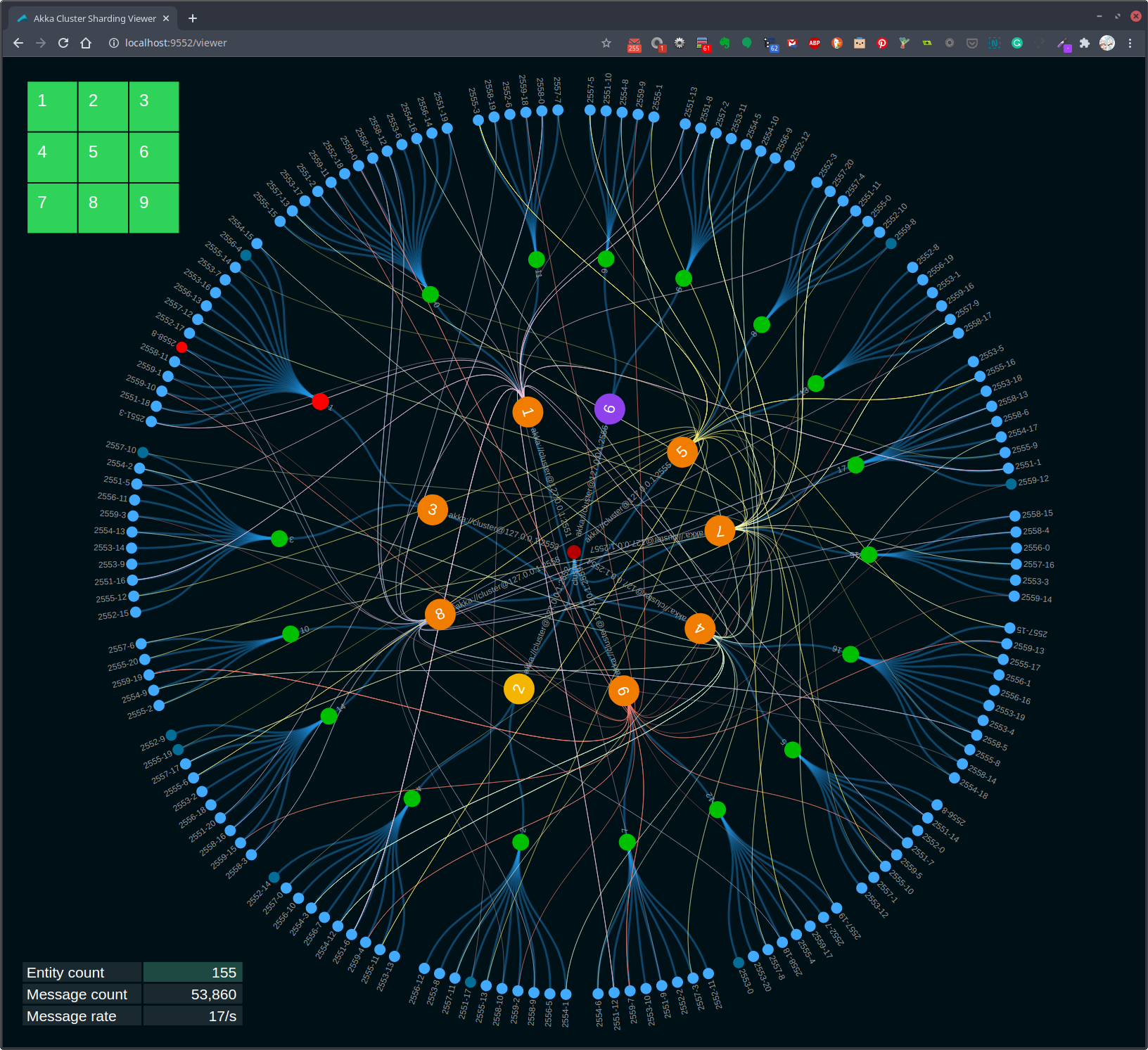
Figure 5, Shard and entity actors after rebalancing
Shards and their associated entity actors may be rebalanced When new nodes are added to the cluster. This rebalancing is done to more evenly distribute the workload across the cluster.
./akka node start 1 3Start node 1 on port 2551, management port 8551, HTTP port 9551
Start node 3 on port 2553, management port 8553, HTTP port 9553
In the above image, cluster nodes 1 and 3 have been restarted. Note that nodes 1 and 3 changed from a gray to green background color in the top-left grid. Once these new nodes have joined the cluster, Akka cluster sharding rebalanced some of the shards to nodes 1 and 3. In this example, shard 1 with the red highlighted entity actor 2558-8 was rebalanced to node 1.
In the sample scenario shown in the above images, we tracked entity actor 2558-8. This entity actor instance started on node 3. When node 3 was stopped, the actor was restarted on node 3. Finally, when nodes 1 and 3 were restarted it triggered a shard rebalance that resulted in entity actor 2558-8being restarted on node 3.
The key point is that all of the recovery and rebalancing was handled by cluster sharding. This dynamic actor allocation is an example of location transparency.
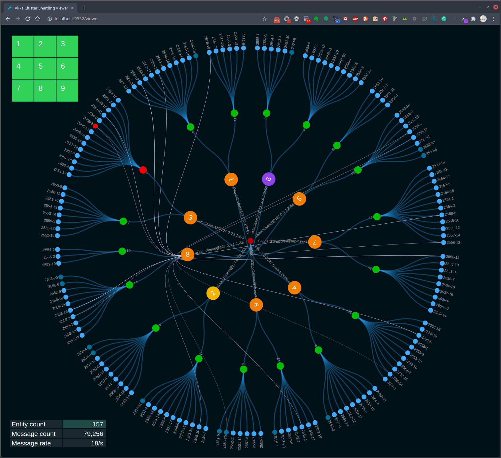
There are a lot of lines drawn in the above images. Note, however, that there are fewer lines shown in Figure 4 than in Figure 5. You can hide some of the lines by clicking each of the large orange circles.
Figure 6, Message lines turned off
In Figure 6 shown above, each of the large circles has been clicked. The now hidden lines show entity command and query messages sent from the EntityCommandActor and the EntityQueryActor.
Figure 6, Message lines turned on node 8
In Figure 6, node 8 was clicked to toggle the message lines on from that node. As you can see in this case, the lines from node 8 are linked to entity circles running on other nodes in the cluster. This is a visualization of Location Transparency.
It is also possible to track a shard and its associated entity actors. Click one of the green shard circles to toggle the tracking.
Figure 7, Message lines turned on node 8
In Figure 7, shard 1 on node 2 is clicked. Note that the shard and its entities are shown in red. Next, node 2 is stopped by clicking it in the top left node grid.
Figure 8, Highlighted shard redistributed
When node 2 is stopped, shard 1 is rebalanced to node 7, as shown above in Figure 8.
