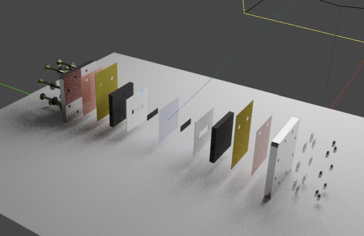
This reference guide and these supplemental materials are associated with this video tutorial.
If you do not have brew ("the missing package manager for macOS") installed on mac, you can follow this link to install it.
Once you have brew installed, you can type (in a terminal):
$ brew cask install blender
Once it is installed you should be able to open it from spotlight and it should be visible alongside your other installed applications.
This tutorial will be via MacOS, I am using a Macbook pro with MacOS Catalina, but Blender is compatible with many (Windows, Linux, openBSD, etc.) operating systems. I have not tested this process and I would not be surprised if some of the keystrokes are different, but overall this installation method should yield results similar to using brew.
Here is a link to the blender website where it can be downloaded.
This order of operations is typically how I approach setting up an animation, there can obviously be some modifications to this, but its just a guideline to not be consumed by the complexity of Blender.
- Import .stl file(s)
- (If needed) Scale to accurate physical dimensions
- Material specification and selection
- Align objects
- If parts are moving (not just camera)
- KeyFrame the first frame
- KeyFrame the last frame
- Determine the camera settings (motion/position of camera)
- Use Eevee render engine while debugging
- Look at the shading in shading mode (adjust lighting)
- Render
In order to distinguish between directions, key presses and selectable options, the following instructions will be denoted by:
- Directions in single quotations:
- e.g. 'Select object with left click'
- Key presses in bold
- e.g. shift + s
- Selectable options
- e.g. Object → Transform → ...
The right arrow symbol (→) is used to indicate progressing through menu sub-levels.
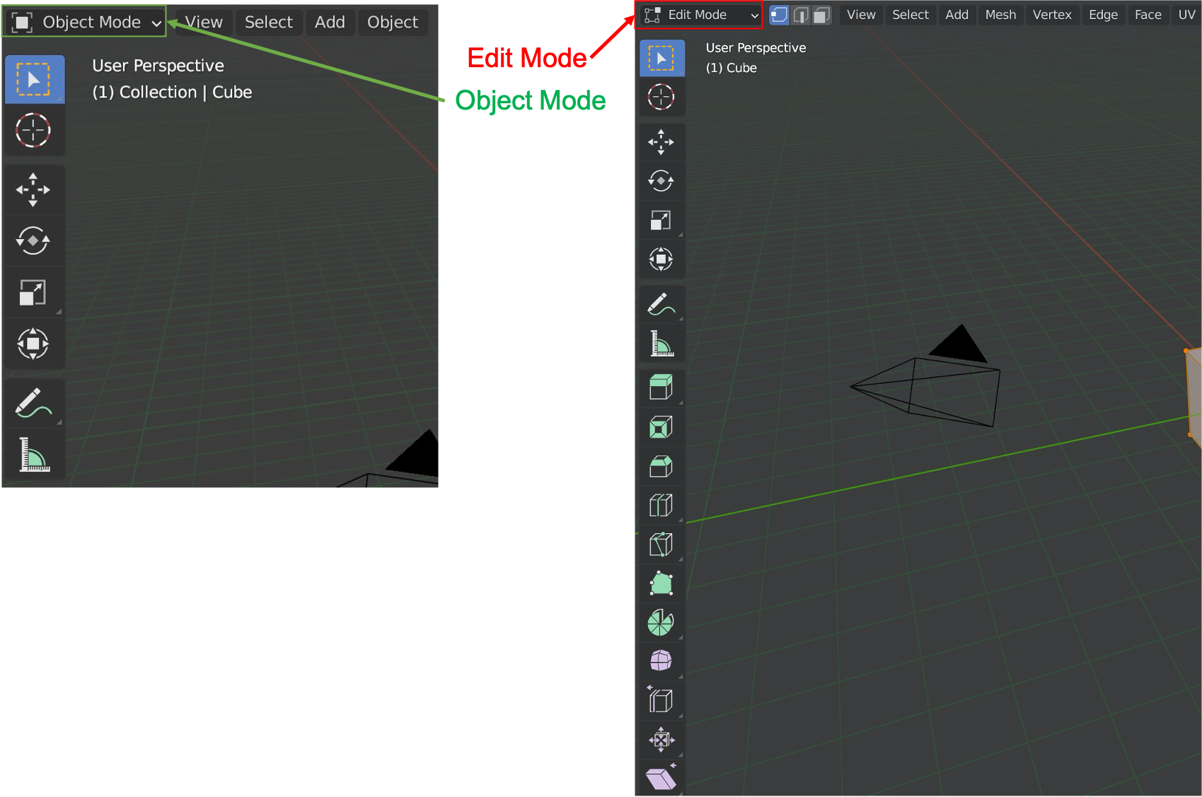
The upper left corner displays which mode is selected:
Toggle between object and edit modes with:
- 'Select object'
- tab
Object mode is the default mode. Edit mode exposes the vertices of an object's mesh so they can be individually selected.
- 'Select object'
- Type g followed by the direction (e.g. gy will allow you to move an object exclusively in the y-direction)
Here is a link to a video explaining how to align objects. You can use it to achieve the equivalent of a 'concentric' constraint in typical CAD software
If an object's origin (shows up as an orange dot) is not in its center of volume see: Setting part origin
Align arbitrary vertices on a mesh:
- Select object
- Go into edit mode (tab)
- Select the vertex (or vertices) with a left-click
- shift + s → move cursor to selected
- Select object to move to the alignment point with a left-click
- shift + s → move selected to cursor
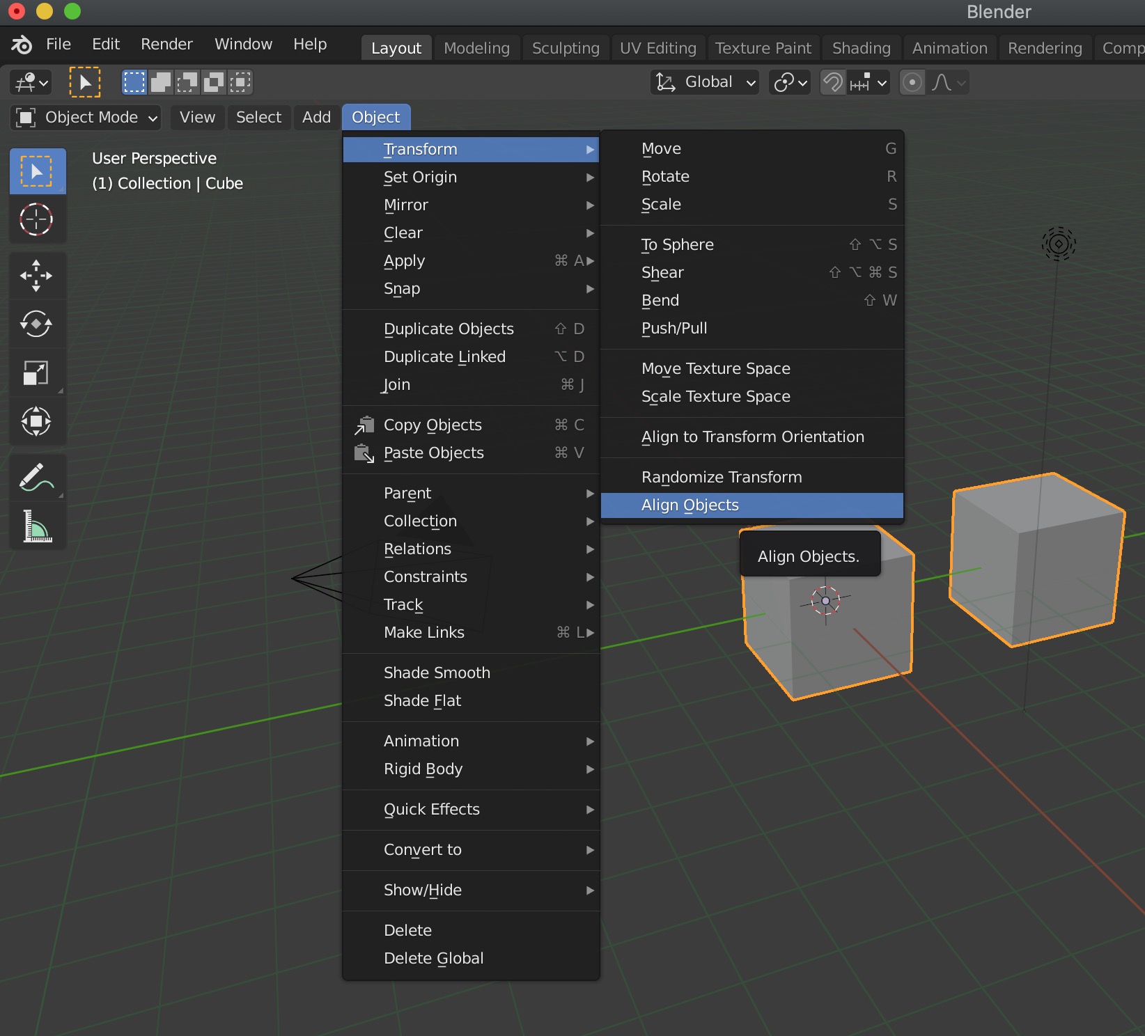
This is to align several objects on a common plane
- Select objects
- In the top left near the top click
- Object → Transform → Align Objects
This opens a dialogue box in the lower left to select which plane, etc.
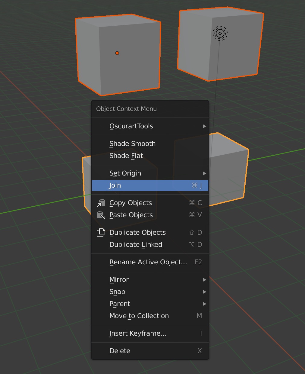
It can simplify certain aspects of a rendering by joining like components together to represent them as a single object in the collection tree (e.g. a set of bolts or washers ...). To achieve this:
- Select multiple objects by 'left-clicking' while holding shift
- 'Right-click' and select join
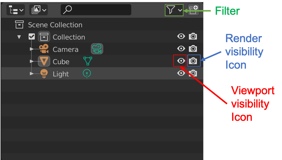
The eye icon toggles objects visibility in the viewport
The camera icon toggles objects visibility in render mode
Note: If the camera icon is not visible it can be made visible with:
- Filter → Disable in renders
This shows the view from the camera
- Numpad 0
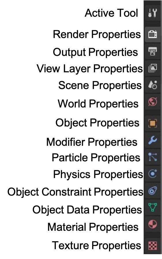
Note that many of the camera settings are accessed by selecting the camera (object) and clicking the Object Data Properties in the Properties Pane (the icon looks like a camera and is where the material icon is for objects and light is for lights)
- to move the camera in camera mode press g (don't hold)
- 'Create a path (curve)' (Object Mode: Add → Curve)
- 'Select follower' (child)
- shift + 'Select path (curve)' (parent)
- ctrl + p
- Follow Path
Now the object will follow this path, but can still have an offset from the path. You can use the 3D cursor to center the object on the path.
To cancel the follow path:
- 'Select the camera' (child)
- 'Select transform properties' in the Properties Pane
- Relations
- 'delete parent constraint'
- 'Select the new camera'
- ctrl + Numpad 0
This centers the camera focus toward an object (origin) as it moves
- 'Select the camera'
- (In the Properties Pane): Object constraint properties → Add object constraints → Track to
- Target → 'Select the object for the camera to track'
This is how I created pump tubing without drawing it in CAD software so it would be easier to geometrically manipulate:
- Object mode → Add → Curve → Circle
- Object mode → Add → Curve → Bezier
- In "object data properties" (looks like bezier curve symbol in Properties Pane); geometry → bevel → object → 'select the bezier circle you just created'
- 'Select curve'
- tab
- Object → Convert to → Mesh from curve
Now the spline is converted to a mesh that is cylindrical with a diameter linked to the diameter of the bezier circle
Tip: add another vertex with extrusion
This method will add a vertex past the final vertex, so the selected vertex will become "inner" and not the end vertex
- 'Select curve'
- tab (enter edit mode)
- 'select end vertex'
- E (extrude)
Add a plane below a model to catch the shadow the model creates
- Object Mode: Add → Mesh → Plane
This menu has all the options for material specifications.
NOTE: make sure that you have scaled the object to its accurate physical size or light will not interact with it the way you expect
- In the Properties Pane → Material Properties
Keyframes attach objects to 3D space at specific times. These instructions are for basic (linear space-time) motion between orientation time1 and time2.
- 'Select an object'
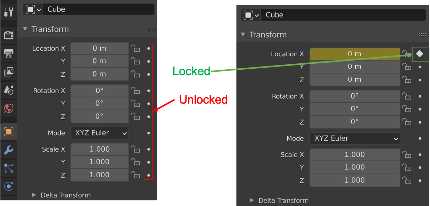
- In the Properties pane click 'Object Properties'; This will show the location, rotation, mode and scale.
- To the right of these are locks and diamonds
- The slider at the bottom of the screen is associated with the time of the animation (note that the frames per-second will determine how many seconds each frame is [Default is 24 frames per second])
- 'Adjust the slider to the time you want to orient the object' (time1)
- 'Click the circle to the right of the lock' to lock object's position (or rotation, or scale) in the frame
- 'Move the slider to time2
- 'move / scale / rotate the part' to where it will be at time_2
- 'Select the diamond' again and the object will move (linearly) between the two points in the time which you specified.
Set origin to arbitrary center of mass/volume
- 'Right click' → Set origin center of mass/volume
Set origin to arbitrary mesh vertex:
- tab (Edit mode)
- 'select vertex'
- shift + s → Cursor to selected
- tab (Object mode)
- 'right click the object' → Set origin → Origin to 3D cursor
I used this tutorial to make axisymmetric glass.
The main takeaways are:
- import a 2-dimensional image of the glassware (you can drag and drop (left click) an image from your desktop into blender)
- in object mode: Add → Mesh → Cylinder
- 'scale and align cylinder with image'
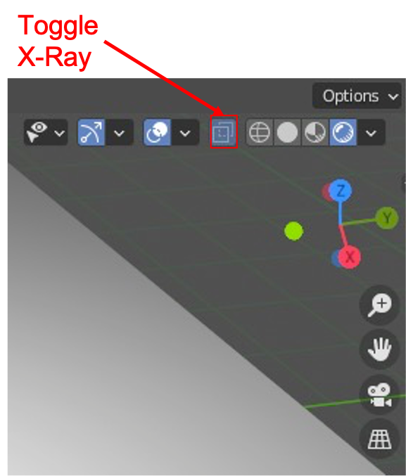
- Note: you should use the orthographic view so that you can align your cylinder correctly. You can select the 2D image and Toggle X-ray to allow selection of vertices behind the object (image).
- tab ('enter edit mode')
- 'Delete top and bottom faces of cylinder'
- 'Select all edge vertices of a face'
- delete
- Faces
- Iterative steps:
- 'select vertex group to extrude' (left click and drag)
- e (extrude)
- 'move vertices in desired direction'
- (when needed): s (scale) 'scale the vertices to make them trace the contour of the image'
- Modifier Properties → Add Modifier → Solidify
- 'Set thickness'
- Material Properties → Surface → Glass BSDF
