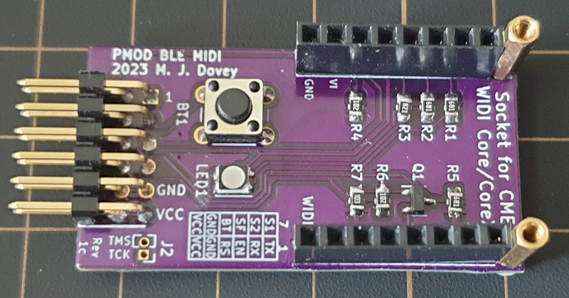
Kicad files for a PCB adapter board/shield to allow the CME Widi Core module to be connected to development boards which use the Digilent PMOD connector.
| PMOD Pin | Core Pin | Notes |
|---|---|---|
| 1 | 1 (TX) | Connects directly to Widi Core TX pin for MIDI over UART |
| 2 | 11 (RX) | Connects directly to Widi Core RX pin for MIDI over UART |
| 3 | 6 (ON) | Connects to Widi Core ON pin via pull down resistor. Active high to enable the Widi Core module. |
| 4 | 12 (RS) | Connects to Widi Core RS pin. Active low reset. |
| 7 | 16 (S1) | Connects to Widi Core S1 pin. Bluetooth connection status (0 = Not connected, 1 = Connected). |
| 8 | 15 (S2) | Connects to Widi Core C2 pin. Bluetooth role (0 = peripheral, 1 = central) |
| 9 | 13 (SF) | Connects to Widi Core SF pin. Baud rate (0 = 31.25 Kb/s, 1 = 100 Kb/s). Requires reset cycle to execute change. |
| 10 | 14 (BT) | If 1, shorts Widi Core BT pin to ground - simulating button press. |
The board also has a push button which shorts Widi Core pin 14 (BT) to ground (for factory reset and bluetooth role change), and an RGB LED, powered by Widi Core pins 2 (LB), 3(LG), 4 (LR) and 5(V3), for status information (see CME Widi Core datasheet, page 9). An optional 0.5 inch pitch header can provide access to the Widi Core pins 9 (TMS) and 10 (TCK)
The BOM includes sockets to allow the CME Widi Core (or the Core N/XN with suitable headers) to be inserted and removed. Alternatively the Core N/XN can be hard soldered for example using 0.1 inch pitch header pins.


