

This document describes the use of the LX34050 inductive position sensor in providing an accurate rotor position for the FOC drive technique. There are two code versions included in this project: LX_LVMC_HURST_FOC_PLL.X uses the PLL estimator for determining all the offsets (sin, cos, and theta), while LX_LVMC_HURST_FOC_Manual.X uses the manual method for obtaining the offsets. Both MPLAB X projects use the same algorithm for calculating the theta from sin and cos signals, and measuring the speed.
Field Oriented Control of a Three-Phase BLDC Motor using a Rotary Inductive Position Sensor application note
- MPLAB® X IDE v5.50
- MPLAB® XC16 Compiler v1.70
- MPLAB® X IDE Plugin: MPLAB® Code Configurator v5.0.3
- MPLAB® X IDE Plugin: X2CScope v.1.0.0
- DFP: dsPIC33CK-MP_DFP v1.8.224
- DSPIC33CK LOW VOLTAGE MOTOR CONTROL (LVMC) DEVELOPMENT BOARD
- LX34050 Static Sensor Board
- Adapter Board
- Target Conductor
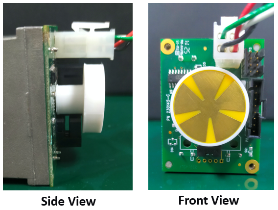
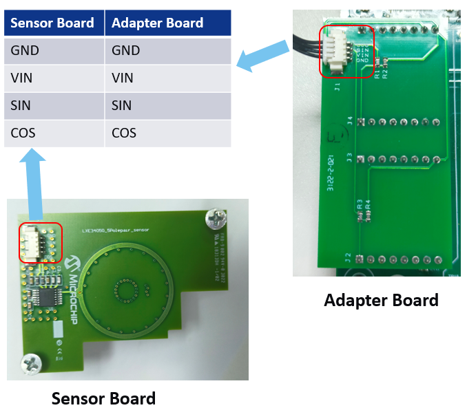
The diagram below illustrates the connection of the LX34050 Integrated circuit and the dsPIC signal controller while the images show the actual placement of the sensor board and target wheel on the hurst motor.

-
Remove the back cover of the short hurst motor and attach the sensor wheel to the shaft as shown in the figure below.
-
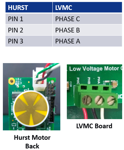
Screw the sensor board and connect the phase winding wires and sensor wires.


- LED11 for telling the direction of rotation.
- Lit up in Clockwise direction and turn off in counterclockwise.
- LED10 for motor status
- Lit up when the motor is running and turn off when the motor is stopped
- SW1 for turning ON/OFF the motor
- SW2 for reversing the direction of the motor.
- This switch button is designed to work only when the motor is stopped.
Tuning or setting the offsets is the first thing that is recommended to be done before running the motor using the LX sensor as feedback. Refer to the LX34050 Inductive Position Sensor-Based Field Oriented Control of Three-Phase BLDC Motor application note for setting the offsets.
Once all the offsets are determined, the system is ready to use the LX34050 sensor as feedback. The calibrated sine and cosine signals are fed to the atan(y/x) function, which calculates for the theta. The calculated theta is added with the theta offset to get the absolute rotor position. The speed is derived from several samples of the difference between subsequent rotor angle(θ) and applied with moving average filter to remove random noises.