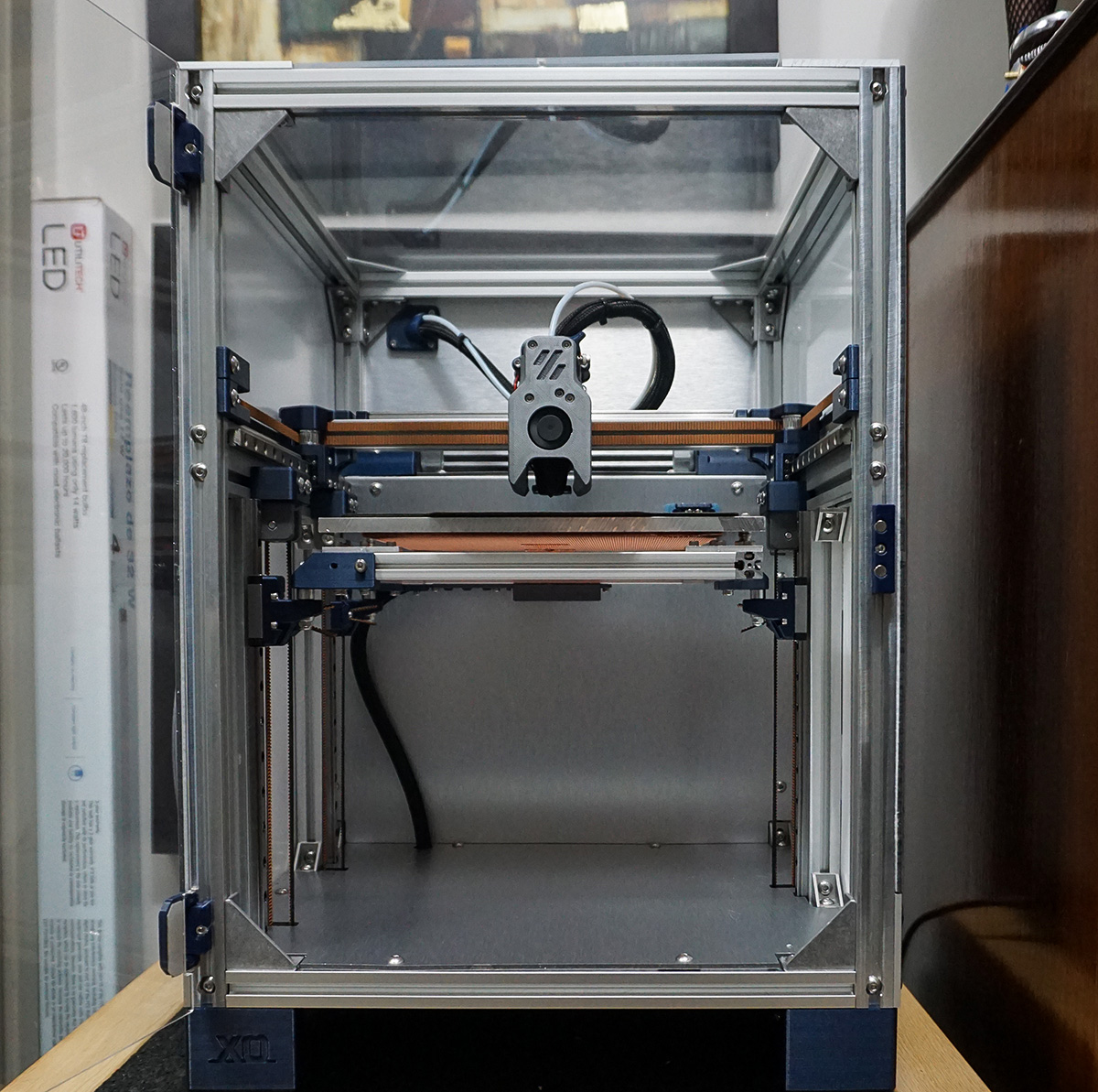
Compact Enclosed Core XY 3D printer with design elements from multiple open-source printers This printer is based on the Voron V.0, Tiny M, and SnakeOil XY printers. It's basically a larger version of a Voron V.0 using 2020 extrusions, and has a 220x220x200 build volume, but the electronics setup from a Trident.
Uses BTT Octopus for MCU, and a Raspberry Pi for Klipper.
Use the Voron Trident documentation to setup the MCU and Klipper, then use my config and klicky files. That should get you up and running, and nearly ready to print. Before printing, make sure to fine tune the clicky dock position.
For more info: https://www.youtube.com/watch?v=fIn6DrubGhQ
A. NEW Toolhead! I am in the process of upgrading to the new Voron V0.2 Mini Stealthburner toolhead! Of course, I modified it to work with the longer Rapido hotend. The basic toolhead parts are the same as the voron version, and I changed up the X carriage to match the new bolt pattern. This means that any V0.2 toolhead will bolt on the carrage, no modified parts are needed like before. Hopefully, this makes it easier to use the stock voron toolhead, or any iteration meant to work with the voron 0.2 carriage mount. The Voron team did a great design on this new version, so I removed the original mini-afterburner from the model. The only changed part on my stealthburner version is the front shroud, and the Rapido hotend mount. Now that the hotend mount is a separate part, it makes it much easier to assemble, and change hotends!
B. Minor corrections to the CAD model were made. notably one of the rear bed carrier brackets, and the Z carriage bearing hole was made a tiny bit smaller in hopes for a tighter fit.
Other than that, there hasn't been much development. Mostly because the printer has been amazing, and I haven't run into any issues that needed to be addressed.
PREVIOUS NOTES BELOW:
- I'm still working on a composite BOM for the major components (like frame parts). I did not render every fastener, screw, bolt, etc. I learned fusion360 as a hobby, and just didn't have the time and skill for a professional rendor like that (sorry!)
- That said - you will need a few packs of M5 bolts (I used button head M5's), and also some M3 (socket head) bolts. Also get the corresponding M5 and M3 drop-in T-nuts. I don't have the exact count on these since I had multiple packs in my stash that I picked from. Typical M5 variety packs should work, but you may need to get a pack of Just longer M5's, from 20mm-40mm for the few longer pieces you will need. you'll also need a few 3mm square nuts for the x carriage mount.
- I'm using 20x40mm corner gussets from Framingtech.com https://www.framingtech.com/20-x-40-gusset at the inside corners of the frame. These are pretty pricey, but they are very well made. You can substitute these with some regular corner brackets if you want to save some money.
- for motors - X and Y can use any typical Nema 17. I used 48mm Motors. For the Z motors, you will need to use the pre-geared Nema 17s, like these: https://www.amazon.com/gp/product/B00WATUFIG/ref=ppx_yo_dt_b_search_asin_title?ie=UTF8&psc=1 These steppers have a built in 5.18:1 gear ratio. The config file will have the correct rotation distance in the Z_stepper section for these to work. The Toolhead uses a 36mm round Nema 14 that is typical to other small extruders, like the orbiter or mini-sherpa.
- The tool head is a modified V0 tool head. it has longer fan ducts for a rapido hotend, and it's 3mm thicker on the front side to account for a 30x30x10mm fan in lieu of a 30x30x7mm fan that is the standard for the V0. You can use the stock V0 in it's place, or any one of the other iterations and mods for this toolhead.
- The X carriage is a little different than the standard voron carriage, as it has accomodations for the clicky probe mount, and also a custom backplate behind the nema motor for wire management. These extra parts can be easily modified to account for different hotends and wiring setups. right now most of the parts have captured nuts, but I will be working on a version with heatset inserts for a future update. Some of the captured nuts I'm using at the sides of the mount are 3mm square nuts. again, this may be updated to heat inserts sometime in the future, when I get around to buying some more.
- The bed frame uses 1515 extrusions and matching corner brackets that I had custom laser cut. There is a dxf file for these triangular brackets that you can send to a 3rd party laser cutting service to have made. I had them made at the same time I had the side panels cut, and used SendCutSend, located in the USA. You can probably aso 3d print these parts as well.
- This IS a work in progress for the most part. If you find any issues, or have questions, please let me know, and I'll do my best to update the files.
