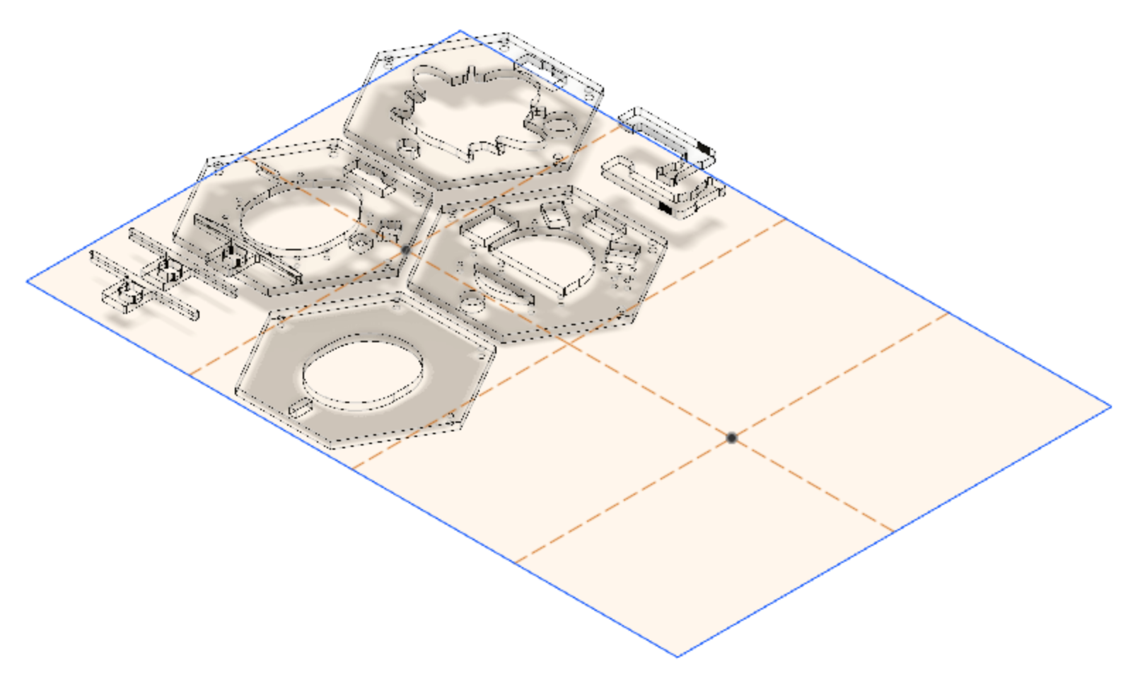
SMBeeHive is a custom programmer for the SMBee project. This is the Fusion 360 design for its case. It can be laser-cut from 3mm clear acrylic.
The design for other components of the SMBeeHive are available here:
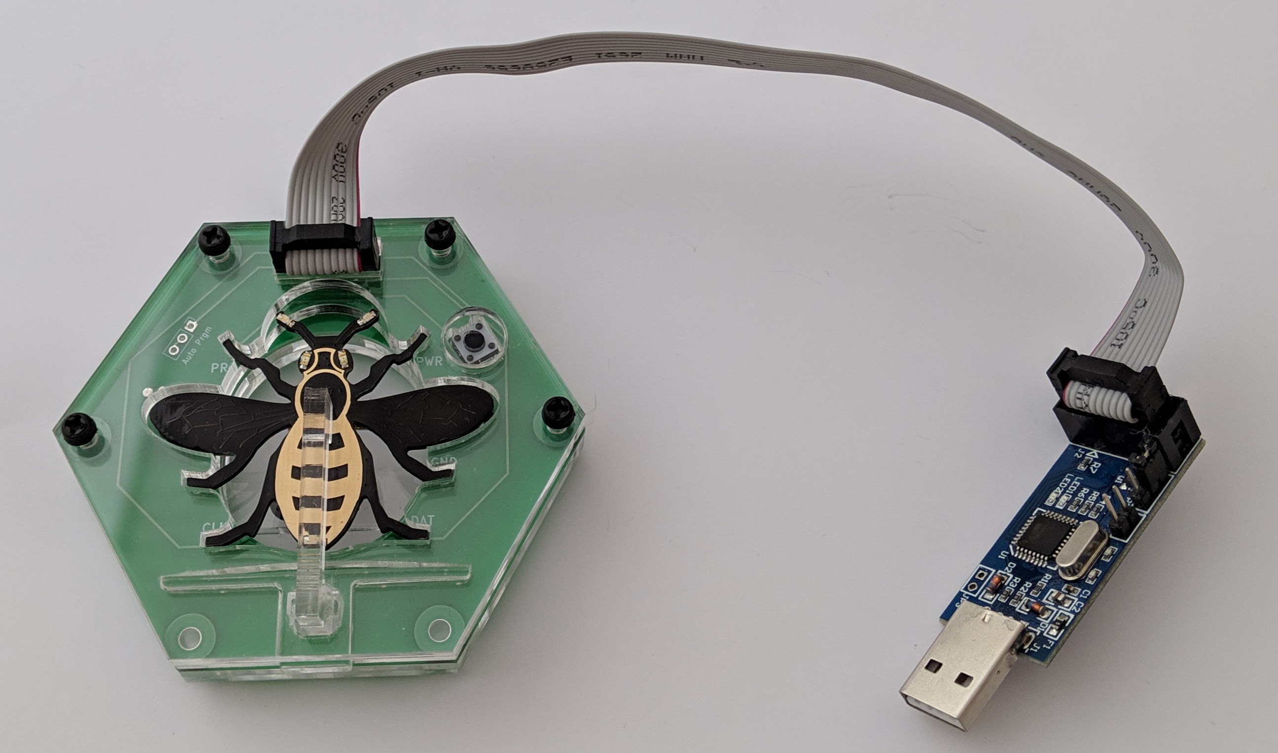
A complete assembled programmer with a docked bee.
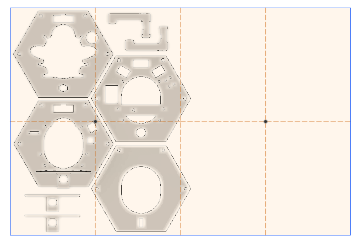
The laser cutter pattern image generated from the 3D design. Rotate the material 180° to cut a second case.
The design is cut from 3mm clear acrylic.
I've been using clear 3mm cast Perspex® with a thickness tolerance of from 2.3mm to 3.7mm. The extruded type has a tighter tolerance. The material is supplied as 600mm x 400mm sheets.
The material will need to be pre cut to 300 x 200mm, a quarter of a sheet. This size is important if you want to cut two cases from a single 300 x 200mm piece.
These are the cut-patterns to support the range of material thicknesses.
You will need a pair of calipers, vernier or digital or similar measuring device. To identify a suitable image peal back the protective film slightly from each corner on both the front and back side and measure the thickness. Take the maximum thickness and choose the next thickness up so for 3.26 choose the 3.3mm image.
| Max measured thickness (mm) |
PDF download |
|---|---|
| 3.7 | SMBeeHivePCB1.2-3.7mm.pdf |
| 3.5 | SMBeeHivePCB1.2-3.5mm.pdf |
| 3.3 | SMBeeHivePCB1.2-3.3mm.pdf |
| 3.1 | SMBeeHivePCB1.2-3.1mm.pdf |
| 2.9 | SMBeeHivePCB1.2-2.9mm.pdf |
| 2.7 | SMBeeHivePCB1.2-2.7mm.pdf |
| 2.5 | SMBeeHivePCB1.2-2.5mm.pdf |
I intend to design a simple gauge that can be cut from a piece of scrap acrylic. This should make it easier to choose the suitable pattern eliminating the need to measure the thickness and take into account the laser cut thickness.
The PDF's are A4 size - 297 x 210mm, the required material size is 300 x 200mm. If the top left of the material is positioned at the laser cuter origin then the cut pattern will be correctly positioned. To position the material for a second cut, rotate the material 180° and again position the top left to the laser cutter origin, repeat the cut with the same pdf image or ome better matching the material thickness.
I've duplicated some parts for spares. You may find the retaining-arm-sprung-latch cut out of the bottom case-layer doesn't cut accurately, it needs to be cut in the correct order so it isn't cut free before its internal cuts, this may not happen. Dispose of it and use one of the others.
The design requires 5 x M3 Coarse (0.5mm pitch) 15mm black nylon pan-head screws. The bottom layer of the case and the battery lock-out cross-piece on the adjacent layer will need to be tapped to create the threads necessary to accept the screws, do this with an M3 coarse (0.5mm pitch) taper tap. An alternative is to drill these holes out to clear the threads and use longer screws and nylon nuts. The screws lengths can be trimmed with side-cutters or a craft knife.
For details of the tap and wrench see: SMbeeHive equipment.
To cut a thread with the tap, screw the tap into the hole with the tap wrench taking care to keep the tap perpendicular to the material, continue to the full length of the tap. Clean the debris from the tap thread, then fully unscrew it to remove.
See the project documentation.
I've been using the Perspex® a brand of clear acrylic from the stock carried by The Making Rooms Blackburn, my local FabLab, it looks very good optically but has poor thickness tolerance. The stocked material is the cheaper cast type rather then extruded, its thickness can vary anywhere from 2.3mm to 3.7mm a difference of 1.4mm. This variation isn't just between sheets, the thickness changes across a single sheet. The uncut sheets measure 600mm x 400mm so although its possible to have this range across a full sheet, with cut area we are working with, for a single case of about 200mm x 160mm the variation within a single case will be a lot less.
The case design is generally tolerant of material thickness with the exception of the retaining arm. The retaining arm fits into a slot through the main body so to be a good fit, this slot and derived dimensions have to be selected for the measured material thickness along with the arm length. To support this I've parametrized the design and generated some PDF format patterns for the laser cutters to cover the thickness range. It does mean however that the overall case height which consists of 4 layers plus the PCB can very between 10.8 and 16.4mm for cast material. The thickest case I've cut so far is 12.8mm and thickest 15.5mm. If you want more consistent results use extruded material (2.85mm to 3.15mm) which would give a more consistent range of case height of 13mm to 14.2mm.
To reduce material waste to a minimum, the project has been designed to work with a sheet size of 300mm x 200mm (1/4 of a full sheet) from which 2 cases can be cut, potentially 8 from a full sheet.
The case was designed in Autodesk Fusion 360 with a free hobby licence however with the crippling of free-licence features, migration to online only access and problems I've had with licence expiry and licence renewal I can no longer recommend Fusion 360 unless there is a paid licence that suits your needs.
I am now migrating to FreeCAD for new projects. FreeCAD unlike Fusion360 supports Linux.
It's not practical to provide a full fusion 360 tutorial on the design but here are the main points you need to modify the design that you won't find in the general Fusion 360 resources.
This is the current fusion 360 case design. You only need it if you want to inspect the design in the Fusion 360 application, customize the case and regenerate the cut patterns.
| F360 archive | PCB | changes |
|---|---|---|
| SMBeeHive1.2.f3z | 1.2 | Initial design and cut pattern drawing for SMBeeHive PCB 1.2 |
From the Fusion 360 app create a suitable project and open this to create the files in your Autodesk project space...
Download and install Fusion 360 free trial you can obtain a free licence on request for non-commercial purposes for use beyond the expiry date. See: How to register for a start-up, hobbyist, or student license for Fusion 360.
The projects f3z file is an archive of the 3D .f3d design file and a linked .f2d drawing file. To open them locally in Fusion 360:
- Open the Fusion 360 left hand slide-out Data panel using the top left 3x3-dot icon.
- Using the
New Projectbutton, create a new project for the files. - Double click the new project to open the empty folder.
- Click
File,Open,Open from my computer... - Navigate to the .f3z file and select
Open - Select
Uploadfrom the new dialogue.
The Design and Cut-drawing will be uploaded to your account and appear in your project folder. From here they can be opened viewing and editing.
To customize the material thickness from the design:
- Select
DESIGNin the left of the toolbar. - Select
MODIFY,Change Parametersfrom the toolbar. - Modify the
Material3mmExpressionin the modal table. - Select
OK.
The design will adjust accordingly.
If you have modified the design, when you view the drawing file in the Fusion 360 app you will be prompted to update the drawing:
- Select update (link icon button in the tab bar) to update the drawing with the design changes as prompted.
- Select from the toolbar:
OutputOutput PDF - Deselect
Line-weights - Select
OK
This is useful if the cut-drawing becomes dissociated from the design, you make breaking changes to the design or you want to create a cut drawing from your own design.
The cut pattern drawing requires that all the layers that were designed in-place as they would be constructed are instead layed out flat with some pieces replicated and from this, a PDF file generated. I did a lot of googling, evaluating utility scripts and trial and error to discover how to achieve this without much success. I finally developed a solution which I'm happy with and supports adjustment of the design with the changes propagating through to the cut drawing. I'll outline the key techniques here.
To support the required functionality you must "Capture the Design History". This is the default operating mode in Fusion 360 so don't disable it otherwise essential features will be disabled like parameterization and linked component copying.
I've created a top level component called "Cut layout" within which I've created a sketch of the uncut material. I've also added some guide lines to the sketch to aid positioning. The "Cut layout" component can be hidden when working on the main design. The sketch is positioned adjacent to main model, once created it can be hidden so its prescience doesn't get in the way of working with the main design.
A Fusion 360 feature we rely on is the ability to make linked copies of components this is implicit behavior when you use MOVE/COPY operation on a Component and select the Create Copy option in the features dialogue. Typically:
- Create your Cut layout component under the root component.
- Activate the Cut layout component: Select the radio-button on the end of its name in the component hierarchy. This will ensure the copied components are created under it.
- Select the component (in the browser) whose outline you would like to copy and press the keyboard short-cut m. The operations dialogue should be displayed.
- Select the
Create Copyoption. - Use the move features to position the component over the sketch of the sheet material you are cutting from. It doesn't bother positioning the component on the sketch plane, it can be above or below but rotate if necessary so the top-view has the correct cut patterns.
- Move operations in Fusion 360 are aggregated so to finalize them after everything is positioned, select
Capture Positionfrom thePOSITIONmenubar menu. This is a dynamic menu, it will only appear when needed.
 |
 |
|---|
The copied components layed out over the sketch of the uncut sheet-material.
Create a drawing from the 3D design:
- From the left side of the menubar select
DRAWING,From Design - Deselect
Full Assembly - Select your Cut layout component.
- Select
Sheet size,A4 (297mm x 210mm) - Select
OK
On the created drawing:
- Select
Orientation,top. - Select
Scale1:1. - Position the image origin (top left) in the correct position at the top left of the page, ignore the drawing boarder and table lines. Remember the material size may not be be the A4 page size.
- Select
OK. - Delete the page boarder and table lines.
Now save the PDF:
- Select from the toolbar:
Output,Output PDF. - Deselect
Line-weights. - Select
OK.
This is another Fusion 360 operation that took me a long time to discover. Although Fusion designs are always stored on the Autodesk cloud and can be shared with named users to view and download, this feature doesn't maintain the link between the 3D design and the drawing, necessary to enable design changes to be propagated to the drawing.
To maintain the link between the 3D design and the drawing the files need to be archived and download from the online repository:
- From the Fusion 360 app show data-pane (top left button).
- On the cut-pattern Drawing file, select the version label of to open the version list.
- Select
View Details on Web. The drawing will open in your browser. - From the download toolbar button menu select
Fusion 360 Archive(only available from the drawing not the 3D design). You will get notification that the archive is being emailed to you.
The .f3z archive will contain both the 3D design and the drawing file.
This work is Copyright © 2019 Mike Longworth
This work is licensed under a Creative Commons Attribution 4.0 International License.


