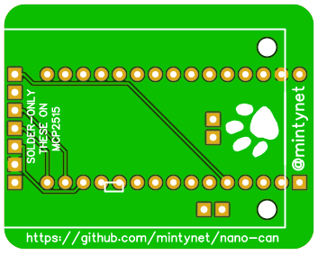
If you would like a nano-can PCB feel free to contact me on Twitter @mintynet, I don't allow msgs if I do not follow you so just tweet asking me to follow back, I will send if you cover the cost of postage.
If you are looking for the BSides Scotland 2019 Badge please click the following link
https://github.com/mintynet/BSidesScotland2019
The sketches below will work but the specific build instructions are in the other repository
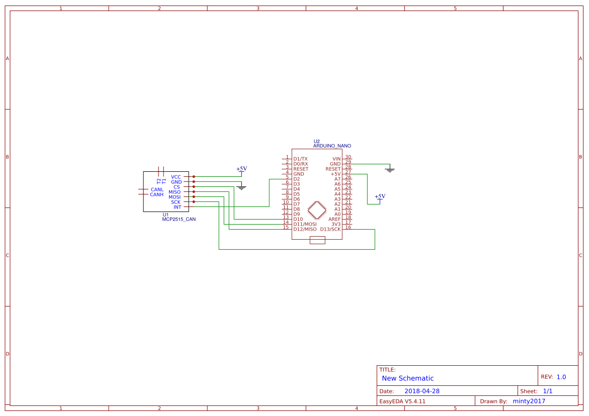
This repository has the arduino code for use with nano can PCB.
These were created as a cheap device for people to get into car hacking.
I take no responsibility for any issues caused if using either the hardware or the code
Requires the use of the following Arduino library
https://github.com/coryjfowler/MCP_CAN_lib
The can-receive-all sketch is the receive example from the above library which will show all messages on the CAN bus. CAN speed can be changed from 500kbps.
CAN messages are shown on the Serial Monitor
This can be used to find interesting messages
The nano-can sketch is configured for the OBD2 port speed (500kbps) and will listen to the can bus starting with CAN ID 0x128. Both can be changed in the code.
Whilst on the Serial Monitor it will show the changes between the messages
u and d will change the CAN ID up or down by 1
U and D will change the CAN ID up or down by 16
h shows the above information
The nano-slcan sketch is slcan compatible software but the serial chip on the arduino boards I use will only run at max 500000bps, 57600bps may be more reliable
EASY EDA PCB Design files
https://easyeda.com/minty2017/nano-can-2019
There is build.md with more detail.
Note:
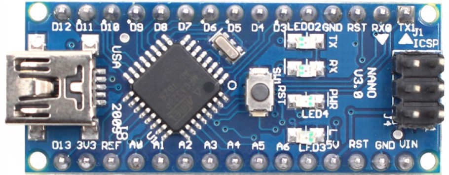
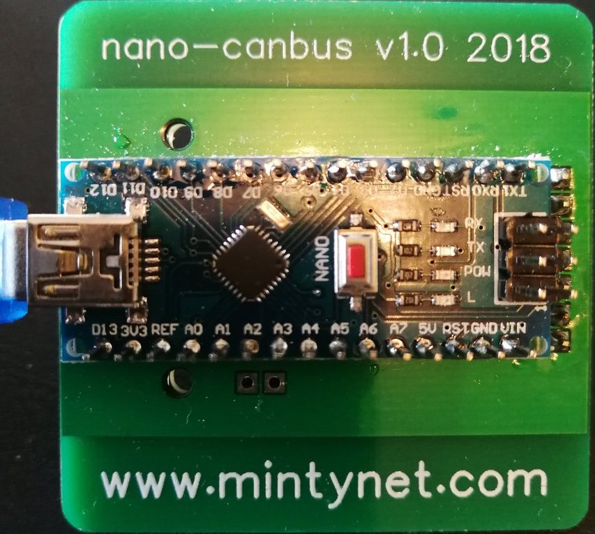
Arduino Nano goes on the top with the URL on, the square at one end denote the position of the USB connector.
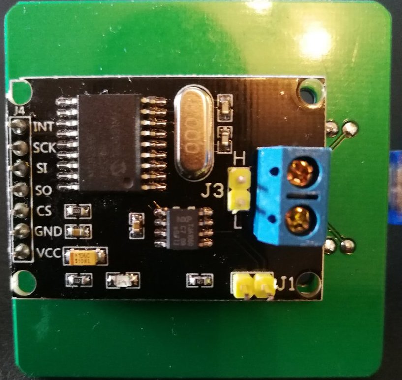
MCP2515 Module goes on the bottom but DO NOT solder the Terminator Jumper or CAN pin headers to the PCB
You may require a jumper on the Terminator resistor
To solder the CAN module to the board, add extra solder to the back of the pins, then heat the pins and push through so that the pins are on the rear, then remove the plastic pin spacer left on the top and add extra solder to the pins.
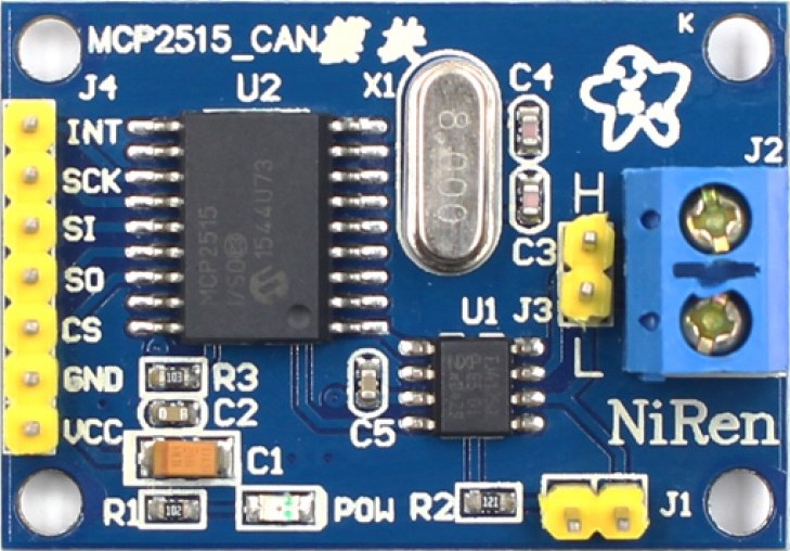
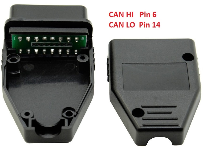
L goes to OBD2 pin 14
H goes to OBD2 pin 6
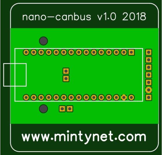
The PCB may look slightly different to the ones shown in this file, white square indicates the USB end of Nano.
Completed v1.0 Top
Completed v1.0 Bottom
OBD2 connector
The PCB may look slightly different to the ones shown in this file, white square indicates the USB end of Nano.
v1.0 PCB Top
v1.0 PCB Bottom
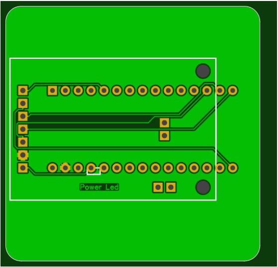
v1.2 PCB Top
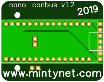
v1.2 PCB Bottom
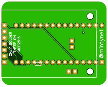
NOTE v1.3 has voltage selector solder pads to select between 3.3v and 5v based Arduino Nano's
v1.3 PCB Top
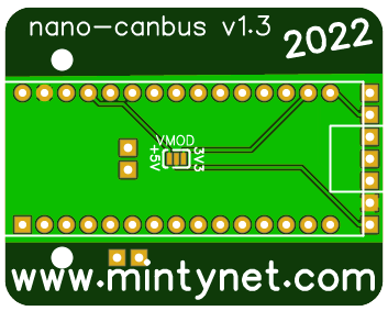
v1.3 PCB Bottom
