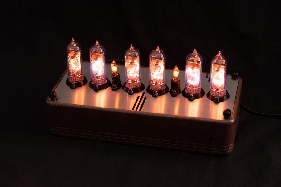
Nixie Clock
This is custom design of a Nixie clock using only integrated circuits (no micro-controller) inspired my various versions of the same design. It uses IN14 tubes.
Rough timeline :
- 2011 initial researches of designs
- 2012 custom PCB designed on Eagle, most components bought
- 2019 PCB redesigned from scratch on Fritzing, manufactured and assembled
- 2020 design and 3D printing of the enclosure, final assembly
What does this repository contains :
- Fritzing schematics + PCB layout
- SolidWorks models
- Various datasheets
A note on the LED controller part : I used an IR controller which I had laying around. It is a common anode controller where the LED I bought are common cathode, this is why my design contains a section to convert the common anode control to a common cathode. This section is not described in the parts list.
Controls
The digits are not always on to extend their lifespan, there is a capacitive touch hidden on the side of the enclosure which will power the tubes for ~15 seconds.
There are two push buttons on the back to set the time.
Flaws
Minutes and hours set
Unlike the other designs, I wired the hours and minutes set buttons between VCC and the CLK input of the third and fifth CD4017 in an attempt to manually control their clock. This does not work because the CLK is already in UP state half of the time (connected to the CARRY-OUT pin of the previous counter). A simple solution is to wire the switchs between CLK of the first counter (after D17) to Q8 (128Hz) and Q4 (2048Hz) outputs of the CD4060, making the clock advance faster.
LED controller output
There are three resistors on the controller output which need to be removed, and instead use a resistor for each LED.
Sources
- Mike's Electric Stuff - Build a Nixie-tube clock
- Peter J. Wendt - My Nixie Clock Project
- Tr1tium - Yet another nixie clock project II
Parts list
Tubes
| part | qty. | notes |
|---|---|---|
| IN14 tubes | 6 | |
| IN3 indicator | 2 | |
| IN14 sockets | 6 | |
| RGB LED | 6 |
1Hz generator
This section generates a 1Hz square signal.
| part | qty. | notes |
|---|---|---|
| 32768Hz crystal oscillator | 1 | |
| 15pF capacitor | 2 | |
| 10MOhm resistor | 1 | |
| 33kOhm resistor | 1 | |
| CD4060 binary counter | 1 | |
| CD4013 dual D flip-flop | 1 |
Dividers
This section successively divides the 1Hz signal by 10, 6, 10, 6 and 3.
| part | qty. | notes |
|---|---|---|
| CD4017 decade counters | 6 | |
| 1N4148 diode | 12 | |
| 100kOhm resistor | 9 |
24h & power-on resets
This section resets all dividers when hiting 24h and also ensure a proper power-on state.
| part | qty. | notes |
|---|---|---|
| BC547 transistor | 2 | |
| 1N4148 diode | 1 | |
| 10uF capacitor | 1 | |
| 2.2MOhm resistor | 2 | |
| 100kOhm resistor | 2 |
Tubes interface
This section connects the counters output to each cathode.
| part | qty. | notes |
|---|---|---|
| MPSA42 transistor | 47 | |
| 33kOhm resistor | 47 | transitor base |
| 33kOhm resistor | 6 | IN-14 current limit |
| 150kOhm resistor | 2 | IN-3 current limit |
Tubes power
This section generates the high voltage power required for the tubes. It also integrates a system to only light the tubes for a few seconds after pressing a button.
| part | qty. | notes |
|---|---|---|
| HVPS1364 power supply | 1 | https://www.shop-tes.com/power-supply |
| 100nF capacitor | 1 | |
| 100nF 250V capacitor | 1 | |
| 39kOhm resistor | 1 | |
| NE555 timer | 1 | used in mono-stable configuration |
| 10uF capacitor | 1 | |
| 10nF capacitor | 1 | |
| 1MOhm resistor | 1 | |
| 100kOhm resistor | 2 |
Misc
This is what I used for interfacing.
| part | qty. | notes |
|---|---|---|
| micro push button | 2 | used to set the minutes and hours by shortcutting the 1Hz to the input of the minutes and hours counter |
| capacitive switch | 1 | connected to the NE555 to light the tubes |
| DC power jack | 1 | |
| lever switch | 1 | |
| IC terminal block | 1 | |
| 2.54mm male & female connectors |
Hardware
| part | qty. | notes |
|---|---|---|
| M3 threaded insert | 8 | |
| M3 blind nut | 16 | |
| M3 standoff | 16 | |
| M3 thumb screw | 4 | |
| M3 screws | 22 |
Manufactured parts
3D printed parts
All printed at home on a Creality Ender 3
- Enclosure, dark wood PLA
- Tubes and indicators holders, black PLA
- Transport cover, white PLA
License
The Fritzing and SolidWorks files are distributed under the Creative Commons 3.0 BY-SA license.