MIDI controlled tape deck. Dynamically adjust the pitch of a recording to a specific pitch based on MIDI note data.
This project is built around the Yamaha KX-130 but can likely be adapted to other decks and mechanisms
Cassette tapes are designed to run at a nominal rate of 1.75 inches per second. When the speed of tape playback is changed, the resulting sound will have a change in pitch. The slower the speed, the lower the pitch, and vice versa. By adjusting the speed of tape playback by a specific amount, the pitch of the recording can be changed to a specific note, assuming the nominal pitch of the recording is known.
This project provides the hardware and software for performing such a task.
In the tape deck used in this project, the tape speed could be adjusted using a 1k potentiometer. The pitch range of the 1k pot was quite limited, meaning that few notes could be reached. Experimentation revealed that the larger the value of the potentiometer, the larger the change in frequency, and thus the more notes that could be tuned to. In addition, the change in pitch as a function of the change of resistance was observed to be linear.
Digital potentiometers are one way of interfacing digital and analog systems. The value of the pot can be changed in software but wired to the tape deck in place of the existing 1k pot. However, digital potentiometers typically have only 128 or 256 "taps" on them, meaning they can only stop at a fairly low number of values between the minimum and maximum values. This is in contrast to the mechanically actuated potentiometer, which can be adjusted continuously along is range.
Due to the low number of taps, a single digital potentiometer would not be able to control the tape deck with enough precision to reach a specific note. In order to mitigate this, two digital potentiometers were ganged together in the circuit shown below.
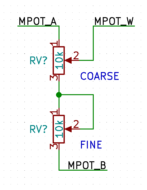
This configuration results in one of the potentiometers causing a larger change in the overall resistance, while the other produced a larger change, creating a "coarse" setting and a "fine" setting. This configuration allowed for a much larger number of frequencies to be reached, as instead of 256 discrete points, there were now 2562 different combinations across the two potentiometers.
The purpose of the potentiometers is to adjust the playback speed of the tape such that the frequency is changed by a target amount. In order to know what values to set the potentiometers to, we must know what the relationship between the potentiometer settings and the change in frequency is in the first place. By understanding this relationship, we can figure out what pot settings we need to obtain the desired change in pitch.
This system has two independent variables--the settings of the coarse and fine potentiometers--and one dependent variable--the change in pitch of the tape. By stepping through a range of combinations of potentiometers settings and recording the resulting pitch shift, we can start to see the relationship develop.
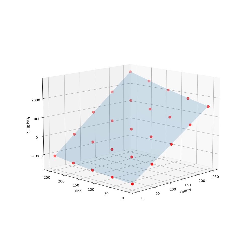
Note that this relationship is only linear when the coarse potentiometer is changed, and is nonlinear when the fine potentiometer is changed. Also note how the coarse potentiometer has a greater impact on the output frequency than the fine potentiometer.
Once we have captured enough data points, a best fit equation can be calculated for the surface using polynomial regression. This is performed in eval/eval.py. This produces a formula that equates the change in output frequency based on the coarse (x) and fine (y) potentiometer settings.
freq(x,y) = -1503.0871471 + 12.0767089x + 0.9015391y + 0.0115233xy + 0.003259y^2
Now that we are able to calculated the change in output frequency for a given combination of coarse and fine settings, we can start to work on the inverse: finding the combination of potentiometer settings that result in the desired change in output frequency.
Solving the equation mathematically for a given frequency is not conducive to an embedded device (or me) so this approach will be a little more brute-force, essentially a recursive guess-and-check.
First, the setting of the fine potentiometer is fixed to 127. A binary search is performed on the setting of the coarse potentiometer, using the equation above to determine what the output frequency will be. Once a coarse settings is found that puts the output close enough to the target value, the same operation is repeated for the fine potentiometer. Essentially the coarse pot is adjust to get the output close, then final adjustment is made using the fine pot.