esm.c:esm_process()
needs (preferably formal) verification.
Good system design is often about knowing what to avoid. Unrestricted use of traditional techniques for writing concurrent software, like preemptive threading1, almost always results in systems that are unpredictable and unreliable. Degradation of those two aspects is specially problematic in embedded systems where predictability and reliability are even more important than performance and/or expressiveness.
Great deal of embedded systems fall into the category of reactive systems, which in short can be described as systems which "react continuously at the speed of the environment"2, as opposed to transformational systems, so systems that "transform a body of input data into a body of output data"2.
As David Harel notices3:
A typical reactive system is not particularly data intensive or calculation-intensive. So what is/was the problem with such systems? In a nutshell, it is the need to provide a clear yet precise description of what the system does, or should do. Specifying its behavior is the real issue.
For these reactive systems, as they are called, the complexity we have to deal with does not stem from complex computations or complex data, but from intricate to-and-from interaction - between the system and its environment and between parts of the system itself.
Most programmers are familiar with flowcharts. Statecharts use the same graphical elements as flowcharts, but the meaning of both is fundamentally different.
David Harel3:
Again and again, one comes across articles and books (many of them related to UML) in which the very same phrases are used to introduce sequence diagrams and statecharts. At one point such a publication might say that “sequence diagrams can be used to specify behavior”, and later it might say that “statecharts can be used to specify behavior”. Sadly, the reader is told nothing about the fundamental difference in nature and usage between the two — that one is a medium for conveying requirements, i.e., the inter- object behavior required of a model, and the other is part of the executable model itself. This obscurity is one of the reasons many naive readers come away confused by the multitude of diagram types in the full UML standard and the lack of clear recommendations about what it means to specify the behavior of a system in a way that can be implemented and executed.
Miro Samek4:
Graphically, compared to state diagrams, flowcharts reverse the sense of vertices and arcs. In a state diagram, the processing is associated with the arcs (transitions), whereas in a flowchart, it is associated with the vertices. A state machine is idle when it sits in a state waiting for an event to occur. A flowchart is busy executing activities when it sits in a node. Figure 2.3 attempts to show that reversal of roles by aligning the arcs of the statecharts with the processing stages of the flowchart.
Support section on 'Visual Paradigm' website5:
People often confuse state diagrams with flowcharts. The figure below shows a comparison of a state diagram with a flowchart. A state machine diagram in the Figure on the left below performs actions in response to explicit events. In contrast, the Activity diagram in the Figure of the right below does not need explicit events but rather transitions from node to node in its graph automatically upon completion of activities.
Active Object Model brings the same improvements to behavioral design as Object Orientation to architectural design. Active objects are objects that encapsulate own flow of control and are designed as message pumps with Run-to-completion (RTC) semantics and explicit state machine structure.
Adapting Active Object Model allows for construction of comprehensible concurrent programs. Resulting conceptual integrity has also added benefit of making it possible to spend effort on design instead of implementation. Implementation step in this method is, for the most part, mechanical process and as such, can be automated.
This repository gathers all the ideas and implementation tricks around lightweight, efficient statecharts and AOM implementation in C. Inspired by QP framework. It's basically a simple cooperative, priority-based scheduler and a (hierarchical) state machine framework. Some implementation techniques and design patterns (like 'Embedded Anchor' and linker-section-based 'plugin' system) are borrowed from Linux kernel.
Another interesting feature is the possibility of running the system without delays, so as fast as possible.
Having the inputs defined explicitly makes mocking them out easy and then linking with the test platform
produces a binary that can generate an execution log containing days worth of system operation in seconds.
Then it's easy to analyze the log (e.g. in an Excel spreadsheet) for safety/liveness properties.
Sort of poor man's model checker 😃.
Provided are following examples/demos:
- simple blink - hierarchical state machine transitioning between two states and reacting to a button press
- Dining Philosophers Problem (DPP) - originally formulated in 1965 by Edsger Dijkstra
- cigarette smokers problem - classical problem originally described in 1971 by Suhas Patil
- pelican crossing simulation - simplest safety-critical system simulation
- producer-consumer simulation - two producers requesting actions on a single resource guarded by a 'bus' module
There are also two more complex apps:
- sk6812 LED strip mood lamp and clock with RTTTL alarms and sunrise simulator
- USB HID keyboard firmware - more lightweight QMK alternative
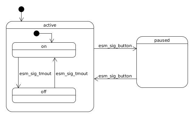
In the form of hierarchical state machine (statechart) the logic of a single 'blinker' is:
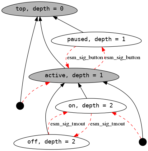
The code implementing this is a set of pointers to structures (black arrows) encoding the hierarchy and pointer assignments in switch/case handlers (transitions - red arrows):
// Blink state machine configuration structure
// It's kept in read-only memory and holds the delay
// the machine will stay in state before transitioning to another

typedef struct {
	const uint32_t delay;
	const uint8_t led_num;
} blink_cfg_t;

// Structure representing the machine object (active object)
// Timer is used to schedule timeout signal on which machine changes state

typedef struct {
	hesm_t esm;
	esm_timer_t timer;
	blink_cfg_t const *const cfg;
} blink_esm_t;

// Define two top-level states (state structures) 'active' and 'paused'

ESM_COMPLEX_STATE(active, top, 1);
ESM_LEAF_STATE(paused, top, 1);

// Define two nested states 'on' and 'off'

ESM_LEAF_STATE(on, active, 2);
ESM_LEAF_STATE(off, active, 2);

static void esm_active_init(esm_t *const esm)
{
	(void)esm;
	ESM_TRANSITION(on);
}

static void esm_active_entry(esm_t *const esm)
{
	(void)esm;
}

static void esm_active_exit(esm_t *const esm)
{
	blink_esm_t *self = ESM_CONTAINER_OF(esm, blink_esm_t, esm);
	esm_timer_rm(&self->timer);
}

static void esm_active_handle(esm_t *const esm, const esm_signal_t * const sig)
{
	(void)esm;

	switch(sig->type)
	{
	case esm_sig_button:
		ESM_TRANSITION(paused);
		break;
	default:
		ESM_TRANSITION(unhandled);
		break;
	}
}

static void esm_on_entry(esm_t *const esm)
{
	blink_esm_t *self = ESM_CONTAINER_OF(esm, blink_esm_t, esm);
	esm_signal_t sig = {
			.type = esm_sig_tmout,
			.sender = esm,
			.receiver = esm
	};
	esm_timer_add(&self->timer,
			self->cfg->delay>>3, &sig);

	BOARD_LED_ON(self->cfg->led_num);
}

static void esm_on_exit(esm_t *const esm)
{
	(void)esm;
}

static void esm_on_handle(esm_t *const esm, const esm_signal_t * const sig)
{
	switch(sig->type)
	{
	case esm_sig_tmout:
		ESM_TRANSITION(off);
		break;
	default:
		ESM_TRANSITION(unhandled);
		break;
	}
}

static void esm_off_entry(esm_t *const esm)
{
	blink_esm_t *self = ESM_CONTAINER_OF(esm, blink_esm_t, esm);
	esm_signal_t sig = {
			.type = esm_sig_tmout,
			.sender = esm,
			.receiver = esm
	};
	esm_timer_add(&self->timer,
			self->cfg->delay, &sig);
	BOARD_LED_OFF(self->cfg->led_num);
}

static void esm_off_exit(esm_t *const esm)
{
	(void)esm;
}

static void esm_off_handle(esm_t *const esm, const esm_signal_t * const sig)
{
	switch(sig->type)
	{
	case esm_sig_tmout:
		ESM_TRANSITION(on);
		break;
	default:
		ESM_TRANSITION(unhandled);
		break;
	}
}

static void esm_paused_entry(esm_t *const esm)
{
	blink_esm_t *self = ESM_CONTAINER_OF(esm, blink_esm_t, esm);
	BOARD_LED_OFF(self->cfg->led_num);
}

static void esm_paused_exit(esm_t *const esm)
{
	(void)esm;
}

static void esm_paused_handle(esm_t *const esm, const esm_signal_t * const sig)
{
	switch(sig->type)
	{
	case esm_sig_button:
		ESM_TRANSITION(active);
		break;
	default:
		ESM_TRANSITION(unhandled);
		break;
	}
}

static void esm_blink_init(esm_t *const esm)
{
	ESM_TRANSITION(active);
}

// Configuration structure of machine instance 'blink_1'
static const blink_cfg_t blink1_cfg = {
		.delay = 300UL,
		.led_num = 0
};

// Register instance 'blink_1' of the blink machine with the framework
ESM_COMPLEX_REGISTER(blink, blink1, esm_gr_blinkers, 2, 3, 0);Books:
Articles:
-
Managing Concurrency in Complex Embedded Systems - also all the articles from here
Standard CMake routine with some configuration options. Currently most extensively tested with:
cmake version 3.16.3
arm-none-eabi-gcc (15:9-2019-q4-0ubuntu1) 9.2.1 20191025
libnewlib-arm-none-eabi 3.3.0-0ubuntu1
Project setup for native Linux:
mkdir build
cd build
cmake -DCMAKE_BUILD_TYPE=Debug ..
Project setup for test mode on Linux:
mkdir build
cd build
cmake -DCMAKE_BUILD_TYPE=Debug -DESM_PLATFORM=test -DESM_BOARD=native ..
For STM32 target (bluepill board):
mkdir build
cd build
cmake -DCMAKE_BUILD_TYPE=Release -DESM_PLATFORM=stm32 -DESM_BOARD=bluepill \
      -DCMAKE_TOOLCHAIN_FILE=../platform/stm32/Toolchain.cmake ..
Build step:
make- adding hierarchical state machine support
- add proper platform (BSP) separation
- change to more flexible build system (CMake)
- evaluate usefulness of publish-subscribe (efficient implementation limits signal types to 31)
- switch from array to list in main scheduler loop
- research and implement efficient priority support
- add more examples
- handle timer rollover
- add automatic tests
- MPLv2
If you have questions, contact Mariusz Ryndzionek at:

