Simple MATLAB and CUDA implementations of the frequency-dependent F-number [1], [2] for coherent plane-wave compounding.
The F-number is a user-defined parameter of a technique known as "dynamic receive aperture". Such apertures reduce image artifacts in all image formation methods using the delay-and-sum (DAS) algorithm, such as
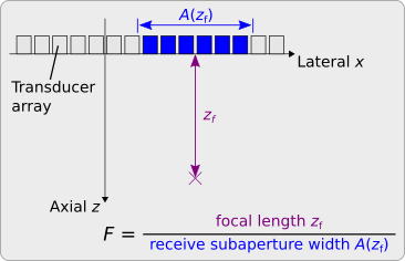
The receive aperture widens with the focal length. The F-number, for a uniform linear transducer array, equals the quotient of the focal length and the width of the receive subaperture.
The usage of a fixed F-number results in a dynamic receive subaperture whose width increases with the focal length.
Established methods to compute the optimal F-number attribute the image artifacts to two different phenomena:
-
Noise [5], [6], [3]: The directivity of the array elements attenuates the echoes and reduces the signal-to-noise ratio of the recorded signals.
-
Grating lobes [7], [8]: The width of the receive subaperture determines the grating lobe-to-main lobe ratio.
Both approaches, although yielding similar F-numbers (0.5 <= F <= 2), are mutually contradictory.
Wide array elements, for example, show
an increased directivity.
The "Noise" approach suggests
the usage of
narrow receive subapertures or, equivalently,
large F-numbers for
such elements to improve
the signal-to-noise ratio.
The "Grating lobes" approach, in contrast, permits
wide receive subapertures or, equivalently,
small F-numbers for
such elements because they attenuate
the grating lobes.
Both approaches, moreover, yield F-numbers that increase with the frequency.
The DAS algorithm, however, requires a fixed F-number and typically uses the maximum F-number at the upper frequency bound. This F-number satifies the conditions for all lower frequencies but, owing to its suboptimal value, reduces the spatial resolution.
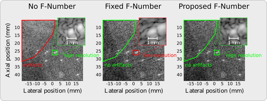
The proposed F-number not only eliminates image artifacts but also maintains the spatial resolution of the full aperture [1], [2].
This F-number, in particular, prevents the first-order grating lobes from insonifying reflective image structures. The F-number, to this end, uses a closed-form expression, which derives from the far-field sensitivity of the focused receive subaperture, to impose a minimum angular distance on these grating lobes.
A Fourier-domain beamforming algorithm enables the usage of frequency-dependent F-numbers. The algorithm not only varies the width of the receive subaperture with the voxel position but also with the frequency. This additional frequency dependence, in contrast to a fixed F-number, includes additional frequency components that improve both the contrast and the spatial resolution.
| Method | Width of the receive subaperture | Spatial resolution | Grating lobe suppression |
|---|---|---|---|
| No F-number | always full | optimal | none |
| Fixed F-number | position-dependent | minimal | exaggerated |
| Proposed F-number | frequency- and position-dependent | almost optimal | optimal |
- Clone the repository or download the release to your local hard drive.
git clone https://github.com/mschiffn/f_number
- Add the repository to your MATLAB path.
addpath( genpath( './f_number' ) )- Run the script "examples.m".
examplesThe repository has the following structure:
.
├── +auxiliary      # auxiliary functions (e.g., dimension and size check)
├── +cuda           # C++/CUDA implementation and MEX interface
├── +f_numbers      # classes for various types of F-numbers (e.g., constant, directivity-derived, proposed)
├── +normalizations # classes for various types of normalizations (e.g., off, on, window-based)
├── +platforms      # classes for various types of platforms (e.g., CPU, GPU)
├── +windows        # classes for various window functions (e.g., boxcar, Hann, Tukey)
├── das_pw.m        # main function
├── data_RF.mat     # experimental data (tissue phantom)
├── examples.m      # examples for the usage of the main function
├── LICENSE         # license file
└── README.md       # this readme
The packages +f_numbers, +normalizations, and +windows contain exemplary class hierarchies to manage various types of F-numbers, normalizations, and window functions.
Use the function das_pw to form images.
In MATLAB type
help das_pwto obtain an explanation of the input and output arguments.
The typical usage is:
[ image, F_number_values ] = das_pw( positions_x, positions_z, data_RF, f_s, theta_incident, element_width, element_pitch, [ f_lb, f_ub ], c_ref, N_samples_shift, window, F_number, normalization, platform );The proposed F-number can be instantiated by
chi_lb = 45;  % minimum angular distance of the first-order grating lobes (°)
F_ub = 3;     % maximum permissible F-number
delta = 10;   % safety margin for anti-lobe aliasing (°)
F_number_rx = f_numbers.grating.angle_lb( chi_lb, F_ub, delta );
The directivity-derived F-numbers [5], [6] are
width_over_pitch = 0.918;  % element width-to-element pitch ratio (1)
F_number_rx_1 = f_numbers.directivity.perrot( width_over_pitch );
F_number_rx_2 = f_numbers.directivity.szabo( width_over_pitch );
The standard fixed F-number is
F_number_rx_3 = f_numbers.constant( 3 );The MEX interface to the C++/CUDA implementation must be compiled:
mexcuda '-L/usr/local/cuda/lib64' -lcudart -lcufft gpu_bf_das_pw_rf.cuYou might have to adapt the library path (here: /usr/local/cuda/lib64) to your system.
-
M. F. Schiffner and G. Schmitz, "Frequency-dependent F-number suppresses grating lobes and improves the lateral resolution in coherent plane-wave compounding," IEEE Trans. Ultrason., Ferroelectr., Freq. Control (2023).
-
M. F. Schiffner and G. Schmitz, "Frequency-dependent F-number increases the contrast and the spatial resolution in fast pulse-echo ultrasound imaging," 2021 IEEE Int. Ultrasonics Symp. (IUS), Xi’an, China, Sep. 2021, pp. 1–4.
-
G. Montaldo, M. Tanter, J. Bercoff, N. Benech, and M. Fink, “Coherent plane-wave compounding for very high frame rate ultrasonography and transient elastography," IEEE Trans. Ultrason., Ferroelectr., Freq. Control, vol. 56, no. 3, pp. 489–506, Mar. 2009.
-
J. A. Jensen, S. I. Nikolov, K. L. Gammelmark, and M. H. Pedersen, “Synthetic aperture ultrasound imaging,” Ultrasonics, vol. 44, Supplement, e5–e15, Dec. 2006.
-
V. Perrot, M. Polichetti, F. Varray, and D. Garcia, “So you think you can DAS? A viewpoint on delay-and-sum beamforming,” Ultrasonics, vol. 111, p. 106 309, Mar. 2021.
-
T. L. Szabo, Diagnostic Ultrasound Imaging: Inside Out, 2nd. Elsevier Academic Press, Dec. 2013
-
B. Delannoy, R. Torguet, C. Bruneel, E. Bridoux, J. M. Rouvaen, and H. Lasota, “Acoustical image reconstruction in parallel-processing analog electronic systems,” J. Appl. Phys., vol. 50, no. 5, pp. 3153–3159, May 1979.
-
C. Bruneel, E. Bridoux, B. Delannoy, B. Nongaillard, J. M. Rouvaen, and R. Torguet, “Effect of spatial sampling on an acoustical image reconstruction,” J. Appl. Phys., vol. 49, no. 2, pp. 569–573, Feb. 1978.


