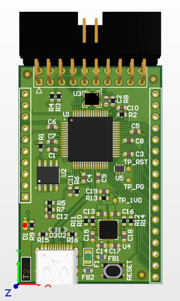
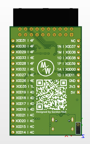
XMOS XU208/XUF208 series minimal system board with USB Type-C port, full XSYS debug port, all pin already breakout to edge of the board.
All using components from Altium-Components-Libraries, this is an open source project focus on refined component management. Classified components with 3D model, easy to use schematic with different package, and also using official recommended layout.
Now we have two shield for this breakout board:
-
XUF208-Clock-Board : Clock generated board with CDCE913 PLL, with I2C interface. Clock output from Y1 pin.
-
XUF208-IO-Board : Four LEDs and four buttons board.
And there have a table for complete plan:
| XUF208-Breakout-Board | XUF208-Clock-Board | XUF208-DAC-Board | XUF208-ADC-Board | XUF208-SPDIF-Board | XUF208-IO-Board |
|---|---|---|---|---|---|
| X0D31(4F) | |||||
| X0D30(4F) | |||||
| X0D29(4F) | |||||
| X0D33(4E) | |||||
| X0D28(4F) | -> I2C_SCL | -> I2C_SCL | -> I2C_SCL | ||
| X0D32(4E) | |||||
| X0D27(4E) | |||||
| X0D26(4E) | <-> I2C_SDA | <-> I2C_SDA | <-> I2C_SDA | ||
| X0D35(1L) | <- MCLK | -> MCLK | -> MCLK | -> MCLK | |
| X0D19(4D) | <- BUTTON_1 | ||||
| X0D18(4D) | <- BUTTON_2 | ||||
| X0D17(4D) | <- BUTTON_3 | ||||
| X0D16(4D) | <- BUTTON_4 | ||||
| X0D21(4C) | -> LED_1 | ||||
| X0D20(4C) | -> LED_2 | ||||
| X0D15(4C) | -> LED_3 | ||||
| X0D14(4C) | -> LED_4 | ||||
| - | - | - | - | - | - |
| X0D37(1N) | -> LRCLK | -> LRCLK | |||
| X0D36(1M) | -> BCLK | -> BCLK | |||
| X0D38(1O) | -> DIN | ||||
| X0D39(1P) | <-DOUT | ||||
| X0D00(1A) | <- S/PDIF_RX | ||||
| X0D11(1D) | -> S/PDIF_TX |
Note:
->means Input (for shield itself)
<-means Output (for shield itself)
<->means Bidirectional (for shield itself)
-means Placeholder
Folder Gerber include gerber files and NC drill files. If your manufacturer using other format or setting for fabrication files, you should not be use those files.
Exported with following settings:
- Unit: Inches
- Format: 2:5
- Output Layout: Plot all layers, except:
- Mechanical 13
- Mechanical 15
- Mechanical 16
- Top Pad Master
- Buttom Pad Master
- Plot all used drill pairs
- Use software arcs
- other setting use default
Note:
Mechanical 1(Gerber/XUF208_Breakout.GM1) for board shape.
Mechanical 17(Gerber/XUF208_Breakout.GM17) for describe impedance detail.
Exported with following settings:
- default
Have fun with it :)

