Intensify3D (Plus) is an easy to use image normalization tool for large scale fluorescent imaging. It corrects heterogeneities in the signal in 3D but also across different experimental samples. Intensify3D yields facilitated visualization and quantification of fluorescent signals.
In short, Intensify3D will first correct for intensity gradients in xy, then match image statistics (see below) across Z and finally match statistics across different samples.
For single stack normalization use intensify3D 1.1
Clone or Download the source code, set the MATLAB_Code directory as the current working directory add to path and run file: User_GUI_Intensify3D.m
Alternatively, there is a complied version (Intensify3D_V2_0_Plus_Installer_web) that can work for users that don't have a MATLAB licence or are looking for a standalone version. Please note that this intaller will download about ~2Gb of libabries needed to run during the installation process.
Follow instruction bellow as well as test data instructions.
Before starting, to understand the basic concept of intensify3D please read (and cite if used) the manuscript and make sure the assumptions of normalization are met. Intensify3D can correct an unlimited number of images since it operates in a serial manner. Hence, it only supports image sequences. The *.tif files should ideally be unprocessed data in a 12 or 16bit format.
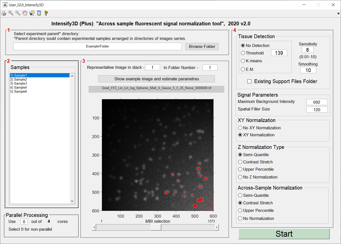
The graphical user interface is divided to 4 panels (steps):
Step 1 – Select parent folder: Here the user selects the directory containing the different image sets (biological samples) divided into directories. Parallel processing section: Is very useful when analyzing large image stacks: the GUI detects how many cores your CPU has and offers the user the option of how many of them will be dedicated to the run. If your MATLAB license does not include the parallelization package, select 0 and work without it (this limitation does not apply to the standalone version).
Step 2 - Shows which directories were found and will be normalized withing and across samples.
Step 3 – Estimate your background: The objective of this section is to assist the user in selecting the ideal maximum background intensity (MBI) in a single image. This value will be used by Intensify3D to estimate the background across all images in the stacks. “Image number” and “Folder Number” are used to select a representative image from the stack that carries a clear signal. Once the image has been selected, pressing the “show image and estimate parameters” button shows the requested image, a brightness contrast adjustment window opens and an initial estimation of the MBI is assigned based on the 99th percentile of intensity potentially showing only signal pixels in red. Next, the user should adjust the MBI selection with the dedicated slide bar at the bottom of the image.
- The matched value for the MBI will be set in the “stack parameters” section in panel 4.
Step 4 – Set run parameters: Automatic Tissue Detection - Intensify3D has the ability to detect the background or tissue area in an image in 2 ways: simply by taking all the pixels above a certain threshold as the tissue, or by clustering algorithms: K means and Expectation Maximization (E.M.). This option is critical for images where not all the image area is relevant for normalization. The sensitivity of the tissue detection should be tested by the user to fit to the specific image set.
- If the process of tissue was already completed to your satisfaction select "Existing Support Files Folder" to save processing time. The rest of the parameters will determine the nature of the signal normalization in xy, xyz and xyz-between folders.
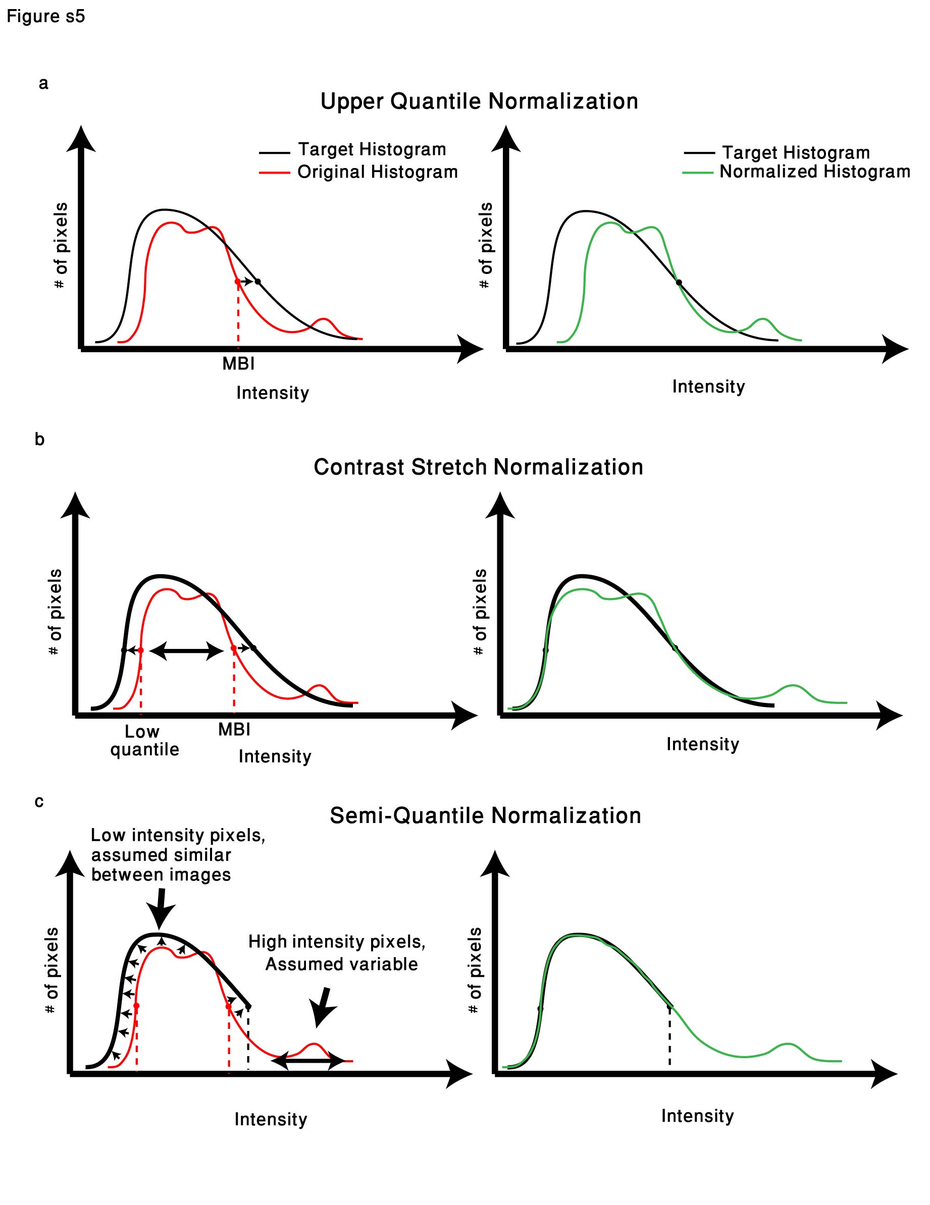
Between-image normalization types and the expected effect on image data Each normalization approach is presented relative to the pixel histogram of the “ideal case” imaging setup (Target histogram). Left/right panels are before/after normalization a. Upper quantile normalization will multiply each image in the stack by a different constant to match the upper quantile (extrapolated from the maximum background intensity) value for the entire stack. b. Contrast stretch normalization linearly transforms each image in the stack so that the lower quantile (25th) and Upper quantile values will match for the entire stack. c. Semi-quantile normalization will force 10000 image quantiles lower than the upper quantile to match across the stack. From the upper quantile and above, the pixels will undergo the contrast stretch correction.
All rights reserved. No part of this software may be reproduced, distributed, or transmitted in any form or by any means, including photocopying, recording, or other electronic or mechanical methods, without the prior written permission of the publisher, except in the case of a citation and certain other noncommercial uses permitted by copyright law.

